33
Diagnostic procedure
Multi Controller
1. Display switch set to position “11”, “12”, “13” and “14”
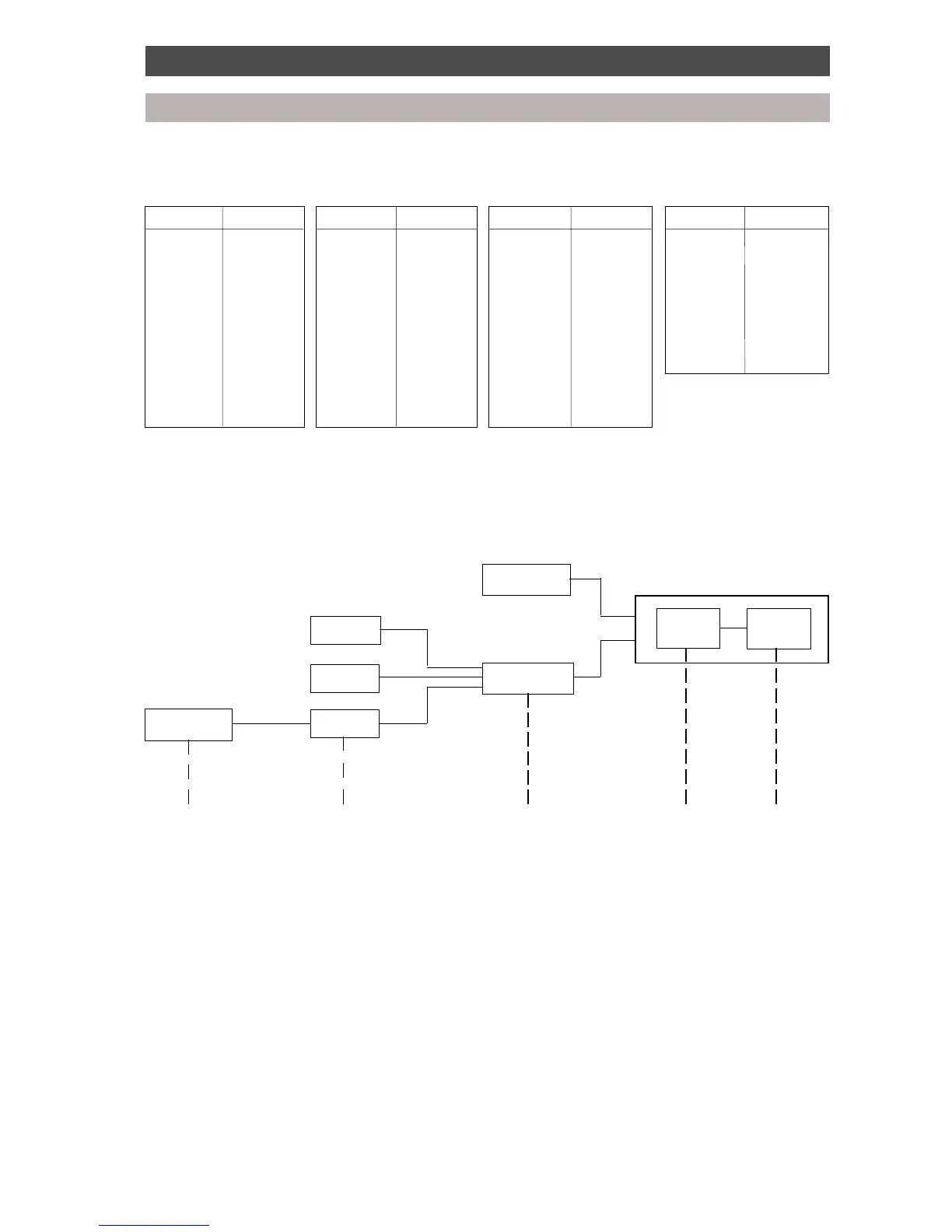
Multi Controller - ThA, B, C, D and X sensor conversion table
Display Temp. °C Display Temp. °C Display Temp. °C Display Temp. °C
18 -10.0 44 1.0 70 12.0 9C 23.0
1C -9.0 48 2.0 74 13.0 A0 24.0
20 -8.0 4C 3.0 78 14.0 A4 25.0
24 -7.0 50 4.0 7C 15.0 A8 26.0
28 -6.0 54 5.0 80 16.0 AC 27.0
2C -5.0 58 6.0 84 17.0 B0 28.0
30 -4.0 5C 7.0 88 18.0 B4 29.0
34 -3.0 60 8.0 8C 19.0 B8 30.0
38 -2.0 64 9.0 90 20.0
3C -1.0 68 10.0 94 21.0
40 0.0 6C 11.0 98 22.0
Display [00] signifies sensor open circuit.
Inverter
control board
INV
Control board communication diagram
Interface
control board
I/F
Multi Controller
M/C (1)
Multi Controller
M/C (2)
Indoor unit
Remote
controller
A few seconds 1 minute 1 minute1 minute
Remote controller fault code display time lapse for system malfunctions
Serial signal abnormalities: Between the I/F and the INV More than 3 minutes
Between the M/C and the I/F More than 2 minutes
Between the indoor unit and the M/C More than 1 minute
Between the remote controller and indoor unit A few seconds
INV abnormality: More than 3 minutes
I/F abnormality: More than 2 minutes
M/C and indoor unit abnormality: More than 1 minute
 Loading...