– 185 –
Check code
Location
of
detection
Description System status
Error detection
condition(s)
Check items (locations)
Main
remote
controller
Outdoor 7-segment display
Check
code
Sub-code
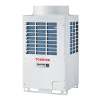
L29 L29
Symbol O signifies
site of IPDU error.
I/F Error in No. of
IPDUs
All stop Insufficient number of IPDUs
are detected when power is
turned on.
• Check model setting of
P.C. board for servicing
outdoor I/F P.C. board.
• Check connection of UART
communication connector.
• Check A3-IPDU, fan IPDU,
and I/F P.C. board for
defect.
L30 L30
Detected indoor address
Indoor
unit
External
interlock of
indoor unit
Stop of
corresponding
unit
• Signal is present at
external error input
terminal (CN80) for 1
minute.
When external device is
connected to CN80
connector:
1) Check for defect in
external device.
2) Check for defect in indoor
P.C. board.
When external device is not
connected to CN80
connector:
1) Check for defect in indoor
P.C. board.
– L31 –
I/F Extended IC
error
Continued
operation
There is part failure in P.C.
board (I/F).
Check outdoor P.C. board
(I/F).
P01 – –
Indoor
unit
Indoor fan
motor error
Stop of
corresponding
unit
• Check the lock of fan motor
(AC fan).
• Check wiring.
P03 P03 –
I/F Discharge
temperature
TD1 error
All stop Discharge temperature (TD1)
exceeds 115°C.
• Check outdoor service
valves (gas side, liquid
side) to confirm full
opening.
• Check outdoor PMVs
(PMV1, 2, 4) for clogging.
• Check resistance
characteristics of TD1
sensor.
• Check for insufficiency in
refrigerant quantity.
• Check for defect in 4-way
valve.
• Check for leakage of SV4
circuit.
• Check SV4 circuit (wiring
or installation error in
SV41, SV42 or SV43).
A3-IPDU
Fan
IPDU
O
O
O
O
O
O
O
O
231
O
O
O
O
O
O
O
O
O
O
O
O
O
O
O
O
O
O
O
O
O
O
O
O
01
02
03
04
05
06
07
08
09
0A
0B
0C
0D
0E
0F
 Loading...