– 62 –
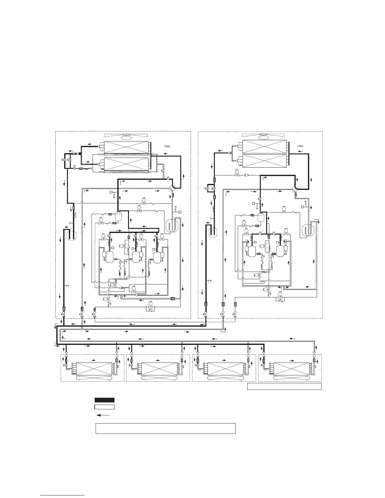
4 Combined Refrigerant Piping System
Schematic Diagrams
4-1. Normal Operation (COOL Mode / DEFROST Mode) -
High Outside Air Temperature (Roughly 20°C or
Above)
)*4021PAM-YMM( tinu rewolloF)*4061PAM-YMM( tinu redaeH
High-pressure gas or condensate liquid refrigerant
Evaporative gas refrigerant (low-pressure gas)
Normal refrigerant line
TL
PMV1
4-Way valve
4-Way valve
TD2
TS1
SV2
TE1
FM
SV3D
PMV2
TK2
SV3B
TK1
SV3A
HPS HPS
HPS
TD1
TK4
SV3E
TK5
SV41
SV42
PMV4
TE2
TD3
SV43
TK3
SV6
TO
SV3F
SV3C
SV
SV
SV
SV
SV
SV
SV
SV
SV
S
V
SV
TL
PMV1
TD2
TS1
SV2
SV5
TE1
FM
SV3D
PMV2
TK2
SV3B
TK1
SV3A
HPS HPS
TD1
TK4
SV3
TK5
SV41
SV42
A3
SV3C
TO
SV
SV
SV
SV
SV
SV
SV
SV
SV
TC2
TCJ
TC1
TC2
TCJ
TC1
TC2
TCJ
TC1
TC2
TCJ
TC1
Balance pipe
Liquid pipe
Liquid pipe
Gas pipe
Gas pipe
PMV
PMV
PMV
PMV
Indoor unit
Pressure sensor
(high pressure)
Liquid tank
Liquid tank
Pressure sensor
(low pressure)
Pressure sensor
(high pressure)
Pressure sensor
(low pressure)
Accumulator
Accumulator
Compressor
1
Compressor
2
Compressor
1
Compressor
2
Compressor
3
O.S.
O.S.
Note: In DEFROST mode, PMV4 also opens.
Note: The "header unit" is the outdoor unit to which the indoor-outdoor communication
line is connected. All other outdoor units are called "follower units".
(The diagram shows a 28 HP system
(16 HP + 12 HP) as an example.)
 Loading...


