22 P9 ASD Quick Start Guide
Typical Connection Diagram
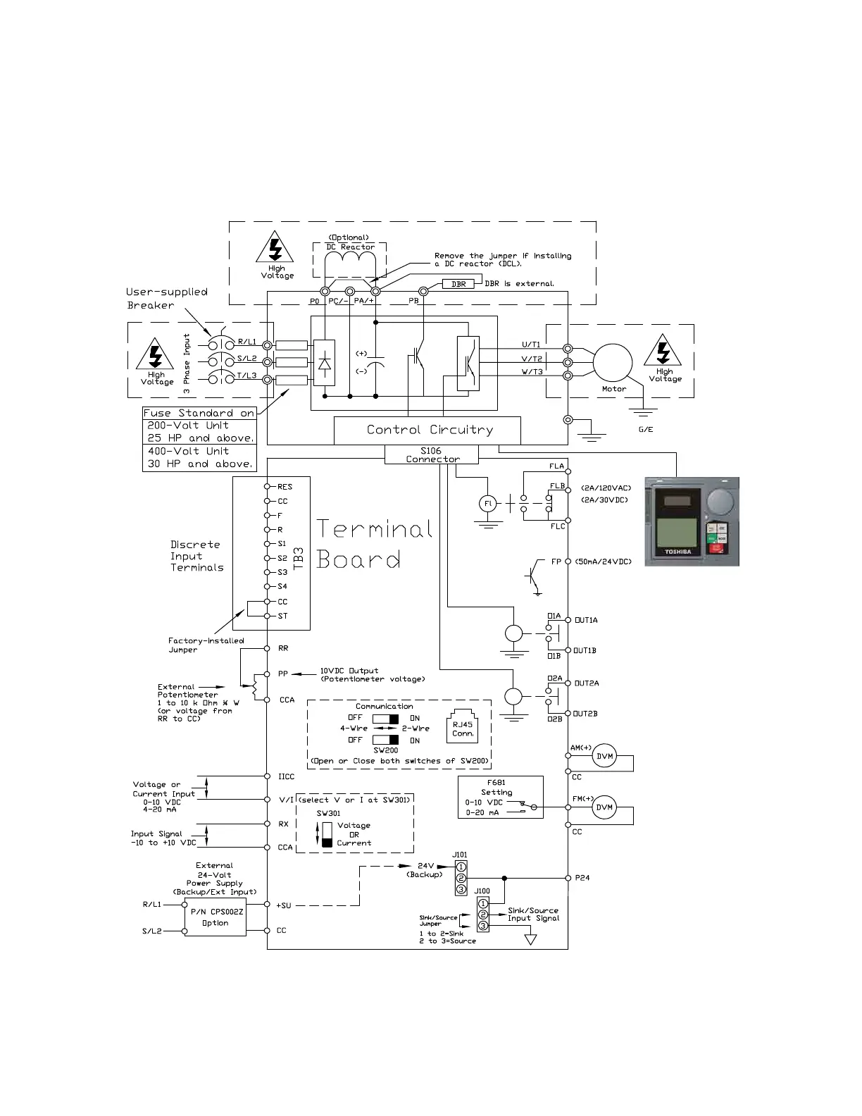
Figure 20. The P9 ASD Typical Connection Diagram.
Note: The AM, FM, and the +SU analog terminals are referenced to CC.
The RR, RX, P24, and the PP analog terminals are referenced to CCA.
The isolated V/I analog terminal references IICC.
Note: When connecting multiple wires to the PA, PB, PC, or PO terminals, do
not connect a solid wire and a stranded wire to the same terminal.
Phone: 800.894.0412 - Fax: 888.723.4773 - Web: www .ctiautomation.net - Email: info@ctiautomation.net
 Loading...