– 15 –
Check items
OPERATION
indicator
Terminal
block
Fuse 3.15A
DC 5V
4. WIRING DIAGRAM
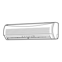
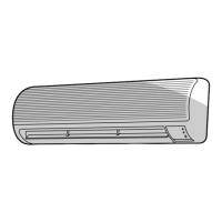
4-1. Indoor Unit
RAS-10JKVP-E, RAS-13JKVP-E
4
3
2
1
Diagnosis result
Check to see if the OPERATION indicator goes on and off
when the main switch or circuit breakers turned on.
(Check the primary and secondary voltage of transformer.)
Check for the voltage between and is AC220 to 240V.
Check for the voltage between and is DC15 to 60V.
Check to the determine if the fuse is open.
(Check TNR.)
Check for the voltage between and terminal of CN13.
Table 4-1-1 Quick check for failure diagnosis
Refer to the service data for the detailed failure diagnosis.
COLOR
IDENTIFICATION
BLK : BLACK
RED : RED
WHI : WHITE
YEL : YELLOW
BLU : BLUE
GRN & : GREEN &
YEL YELLOW
MAIN P.C. BOARD
MCC-891
HEAT EXCHANGER
SENSOR (TC)
CN07
(WHI)
CN13
(WHI)
CN100
(WHI)
CN08
HA JEM-A
MCC-900
Wireless Unit Assembly
POWER SUPPLY
CIRCUIT
21 43
BLK
1
2
3
4
5
6
7
8
9
1
2
3
4
5
6
7
8
9
BLU
BLK
BLU
BLU
BLU
BLU
BLU
BLU
BLU
9
8
7
6
5
4
3
2
1
9
8
7
6
5
4
3
2
1
CN01
(BLU)
CN10
(WHI)
CN33
(WHI)
1
2
1
2
THERMO SENSOR
(TA)
LINE
FILTER
BLK
BLK
BLK
BLK
CN03
(WHI)
1
2
1
2
BLU
1
2
3
4
5
1
2
3
4
5
1
2
1
2
1
2
3
4
5
1
2
3
4
5
LOUVER MOTOR
FAN MOTOR
OUTDOOR
TERMINAL BLOCK
INDOOR
TERMINAL BLOCK
DC MOTOR
WHI
YEL
YEL
YEL
YEL
1 4
2
3
FUSE
F01
1
3
4
5
1
3
4
5
RED
BLK
WHI
YEL
66
BLU
DC5V
DC12V
DB01
CN23
CN21
CN34
CN22
AC 250V
WHI BLK
TNR
21 3
23 1
RED
GRN & YEL
21 3
1 2 3 4
1 2 3 4
1 2 3 4
1 2 3 4
T3.15A
Heat
exchanger
Micro SW
BLU
BRW
(RED)
RED
BRW
BRW
BRW
Ion electride
High-voltage
Power supply
Air purifier
Electrode
1
2
3
4
5
6
1
2
3
4
5
6

 Loading...