– 20 –
7. CONTROL BLOCK DIAGRAM
7-1. Indoor Unit
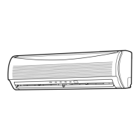
RAS-10JKVP-E, RAS-13JKVP-E
Functions
• Cold draft preventing Function
• 3-minute Delay at Restart for Compressor
• Fan Motor Sarting Control
• Processing
(Temperature Processing)
• Timer
• Serial Signal Communication
M.C.U
Indoor Unit Control Panel
From Outdoor Unit
220-240V/50Hz
220V/60Hz
Serial Signal Communication
(Operation Command abd Information)
Serial Signal Transmitter/Receiver
Micro Switch
Converter
(D.C circuit)
Noise Filter
Indoor
Fan Motor
Air purifier
unit
Louver
Motor
Louver Motor
Drive Control
Indoor Fan
Motor Control
Initializing Circuit
Clock Frequency
Oscillator Circuit
Power Supply
Circuit
Infrared Rays, 36.7kHz
Remote Controller
Operation (START/STOP)
Thermo. Setting
Fan Speed Selection
ON TIMER Setting
OFF TIMER Setting
Louver AUTO Swing
Louver Direction Setting
Hi-POWER
SLEEP
Operation Mode Selection
AUTO, COOL, DRY, HEAT, FAN ONLY
REMOTE CONTROLLER
ECO
Air Puriftier
Heat Exchanger Sensor(Tc)
Temperature Sensor(Ta)
Infrared Rays Signal Receiver
and Indication

 Loading...