FILE NO. SVM-05026
– 18 –
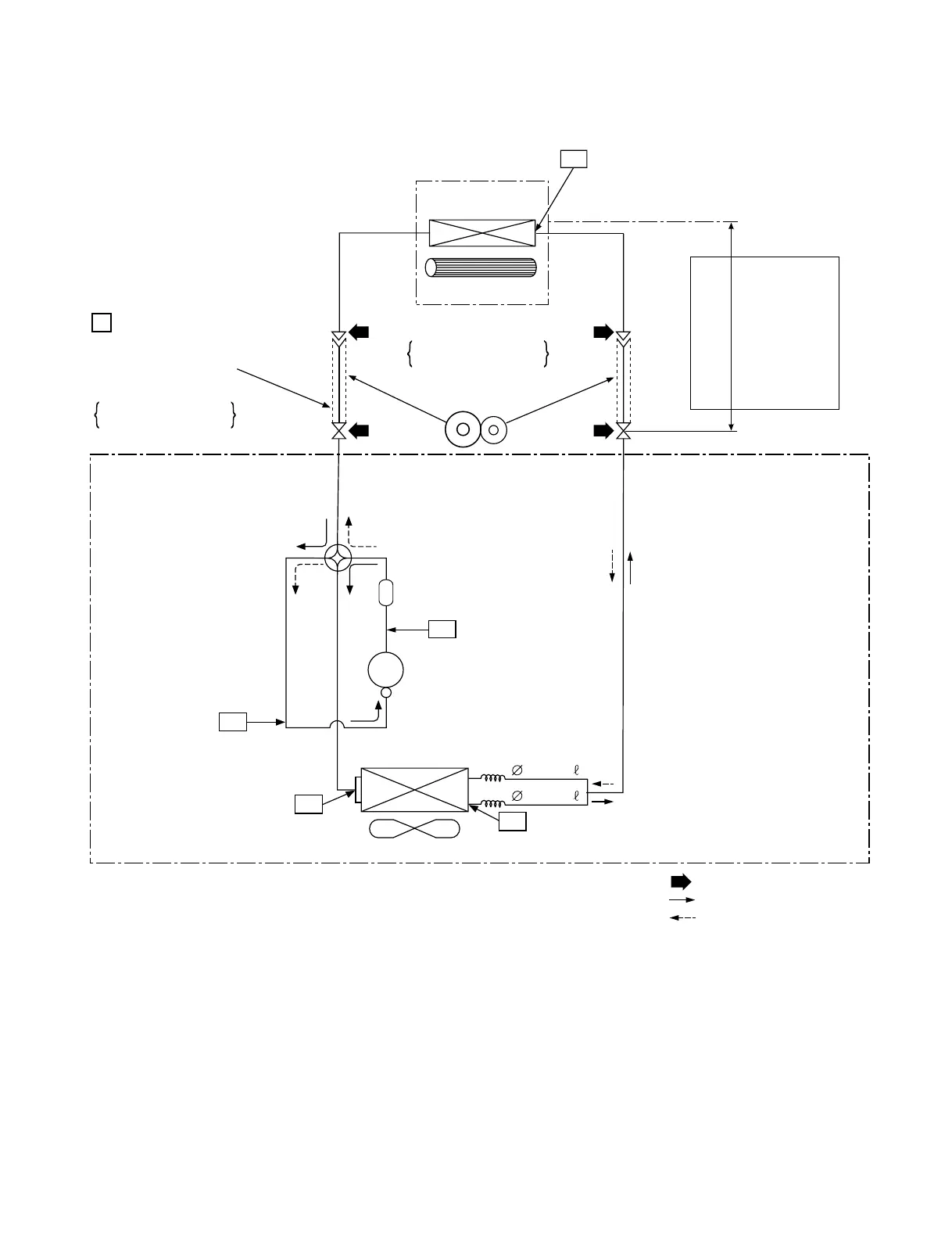
6. REFRIGERANT CYCLE DIAGRAM
6-1. Refrigerant Cycle Diagram
Note :
• The maximum length of the pipe for this air conditioner is 10 m. The additional charging of refrigerant is
unnecessary because this air conditioner is designed with charge-less specification.
Indoor heat
exchanger
Deoxidized copper pipe
Pressure measurement
Gauge attaching port
Vacuum pump connecting port
P
Sectional shape
of heat insulator
Outer dia. : 6.35mm
Thickness : 0.80mm
Deoxidized copper pipe
4-way valve
Outer dia. : 9.52mm
Thickness : 0.80mm
INDOOR UNIT
Cross flow fan
Temp. measurement
Muffler
TD
Compressor
DA89X1F-23F
Split capillary
Refrigerant amount : 0.64kg
NOTE: Gas leak check position
Refrigerant flow (Cooling)
Refrigerant flow (Heating)
Outdoor heat
exchanger
Temp. measurement
Propeller fan
TS
Max. :10m
Allowable height
difference : 8m
Allowable pipe length
T1
T2
TE
OUTDOOR UNIT
1.0x600
1.0x600