Do you have a question about the Toshiba RAS-18N2AX and is the answer not in the manual?
| Brand | Toshiba |
|---|---|
| Model | RAS-18N2AX |
| Category | Air Conditioner |
| Language | English |
Detailed specifications for 18 Class air conditioner models, including cooling and heating capacities.
Detailed specifications for 24 Class air conditioner models, including cooling and heating capacities.
Diagrams illustrating the construction and dimensions of the indoor unit.
Diagrams showing the construction and dimensions of the 24 Class outdoor unit.
Diagrams showing the construction and dimensions of the 18 Class outdoor unit.
Wiring diagram for specific RAS-18UFHP-E5 and RAS-18NAH-E models.
Wiring diagram for specific RAS-18UFP-E5, RAS-18NA-E, RAS-B18UFPX5, RAS-18N2AX models.
Wiring diagram for specific RAS-24UFHP-E5 and RAS-24NAH-E models.
Wiring diagram for specific RAS-24UFP-E5, RAS-24NA-E, RAS-24UFPX5, RAS-24N2AX models.
List of electrical components and their specifications for the indoor unit.
List of electrical components for the RAS-18NAH-E outdoor unit.
List of electrical components for RAS-18NA-E and RAS-18N2AX outdoor units.
List of electrical components for the RAS-24NAH-E outdoor unit.
List of electrical components for RAS-24NA-E and RAS-24N2AX outdoor units.
Refrigeration cycle diagram for RAS-18UFHP-E5 / RAS-18NAH-E models.
Refrigeration cycle diagram for specific RAS-18UFP-E5, RAS-18NA-E, RAS-B18UFPX5, RAS-18N2AX models.
Refrigeration cycle diagram for RAS-24UFHP-E5 / RAS-24NAH-E models.
Refrigeration cycle diagram for specific RAS-24UFP-E5, RAS-24NA-E, RAS-24UFPX5, RAS-24N2AX models.
Control block diagram for RAS-18UFHP-E5 and RAS-24UFHP-E5 models.
Control block diagram for RAS-18UFP-E5, RAS-B18UFPX5, RAS-24UFP-E5, RAS-24UFPX5 models.
Overview of the air conditioner control system, including indoor and outdoor unit roles.
Detailed description of Cooling, Dry, Fan Only, and Automatic operation modes.
Description of Hi POWER, High-Temp Limit, Low-Temp Limit, and Defrost operations.
Explanation of the auto restart function and how to set/cancel it.
Details on the self-cleaning function for reducing indoor humidity.
Description of QUIET and COMFORT SLEEP modes for enhanced comfort and energy saving.
Essential safety precautions for qualified personnel during installation.
Diagrams illustrating indoor and outdoor unit installation placements and procedures.
Guidance on selecting installation places and performing indoor unit installation.
Guidance on selecting installation places and performing outdoor unit installation.
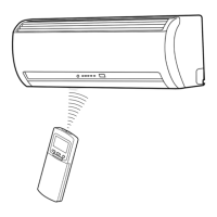
Procedure for setting the remote control selector switch and wiring connections.
Initial troubleshooting steps, basic checks, and primary fault diagnosis.
Guide to using the remote control for self-diagnosis and interpreting check codes.
Flowcharts for diagnosing faulty parts based on symptoms and error codes.
Troubleshooting for indoor unit power, fan motor, compressor, and wiring issues.
Procedures for removing and replacing parts of the indoor unit.
Procedures for replacing components in specific outdoor unit models.
Lists parts for different outdoor unit model series.
Exploded view diagram and parts list for the indoor unit's E-Parts assembly.
Detailed exploded view of the indoor unit components with part numbers.
Exploded view diagrams for various outdoor unit models (RAS-18NAH-E).