2-3-5 E9GA0MA
1-D. Azimuth Alignment of Audio/Con-
trol/ Erase Head
Purpose:
To correct the Azimuth alignment so that the Audio/
Control/Erase Head meets tape tracks properly.
Symptom of Misalignment:
If the position of the Audio/Control/Erase Head is not
properly aligned, the Audio S/N Ratio or Frequency
Response will be poor.
1. Connect the oscilloscope to the audio output jack
on the rear side of the deck.
2. Playback the alignment tape (FL6NS8) and confirm
that the audio signal output level is 8kHz.
3. Adjust Azimuth Adj. Screw so that the output level
on the AC Voltmeter or the waveform on the oscillo-
scope is at maximum. (Fig. M6)
Note: Upon completion of the adjustment of Azimuth
Adj. Screw, check the X Value by pushing the [PRO-
GRAM ] or [PROGRAM ] buttons on the unit
alternately, to check the symmetry of the envelope.
Check the number of pushes to ensure preset posi-
tion. The number of pushes of the [PROGRAM ]
button on the unit to achieve 1/2 level of envelope
should match the number of pushes of the [PRO-
GRAM ] button on the unit from center. If required,
redo the “X Value Alignment.”
1-E. Checking and Alignment of Tape
Path during reversing
Purpose:
To make sure that the tape path is well stabilized dur-
ing reversing.
Symptom of Misalignment:
If the tape path is unstable during reversing, the tape
will be damaged.
Note: Do not use an Alignment Tape for this proce-
dure. If the unit is not correctly aligned, the tape may
be damaged.
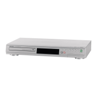
1. Insert a blank cassette tape into the tray and set
the unit to REV. Then confirm if the tape has been
curled up or bent at the Take-up Guide Post[4] or
REV Post[5]. (Refer to Fig. M11 and M12.)
2. When the tape has been curled up or bent, turn the
alignment screw to adjust the height of REV Post.
(Refer to Fig. M11 and M13.)
Take-up Guide Post [4]
REV Post [5]
Fig. M11
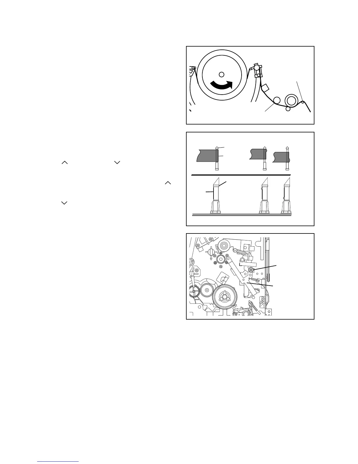
Take-up Guide
Post
Tape
REV Post
Tape
Correct
Incorrect
Fig. M12
Fig. M13
Tape Guide
Assembly
Alignment
Screw
 Loading...