Appendix1. Ethernet Control LAN Network Construction Guide
25
100M Ethernet Control LAN
For the 100M Ethernet Control LAN, basically the transmission line configuration specified in the
IEEE802.3u is used.
If OIS-DS and SVR-DS are installed at a place such as an operator room with good environment (e.g. low
noise), twisted pair cables are used in wiring within the operator room.
Since PCS-DS is installed at site or in a control room, twisted pair cables are used for internal wiring to
connect the PCS-DS main unit to hubs or FX-TX conversion modules to minimize the effect of noises. For
external wiring, optical fiber cables are used.
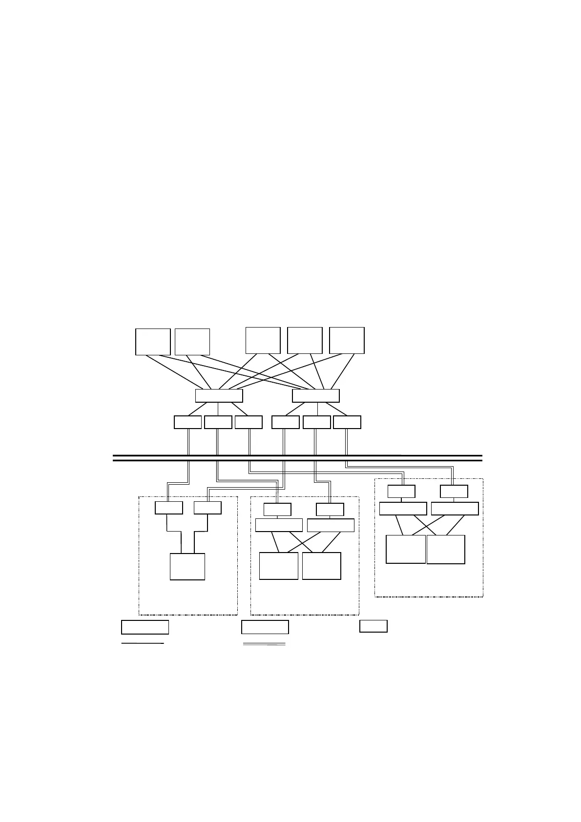
System Configuration
The standard system configuration is a redundant configuration with two systems of transmission lines.
Figure 3.5 is an example of system configuration.
DPCS
Emulator
DPCS Redundant Cabinet
DPCS Cabinet
TX Switching Hub
FX-TX Conversion Module
DPCS
Emulator
DPCS
Emulator
TX-SHUB
TX-SHUB
FX-TX
Twisted Pair Cable Optical Fiber Cable
TX-SHUB
TX Hub
TX-HUB
PCS-DS Redundant Cabinet
PCS-DS
PCS-DS
TX-HUB TX-HUB
Field
Operator Room
SVR-DS
SVR-DS
OIS-DS
OIS-DS
OIS-DS
FX-TX FX-TX FX-TX
FX-TXFX-TXFX-TX
TX-SHUB
TX-SHUB
FX-TX FX-TX
FX-TX FX-TX
FX-TXFX-TX
Figure A1.5 Transmission Line Redundant Configuration
 Loading...


