INTERFACE MANUAL
4.7 Digital Output Signal
Designation Digital output signal
DO_1 ~ DO_24, DO_25 ~ DO_32 (system output signals)
Connector output
terminal
Signals DO_1 ~ DO_16 are assigned to CN6–1 ~ 8 pins and
20 ~ 27 pins. (See Fig. 4.3 and 4.4.)
DO–15 and 16 can be used as SV–RDY and BT_ALM by
changing the user parameter.
DO_17 ~ DO_24 are assigned to CN12–6 ~ 9 pins and 19 ~
22 pins. (See Fig. 4.5 and 4.6.)
The system output signals assigned to CN6–9 ~ 12 pins and
28 ~ 31 pins can be used as signals DO_25 ~ DO_32 by
changing the user parameter.
Function ON/OFF of signals DO_1 ~ DO_32 and pulse output can be
performed by the robot program (BCDOUT command and
PULOUT command).
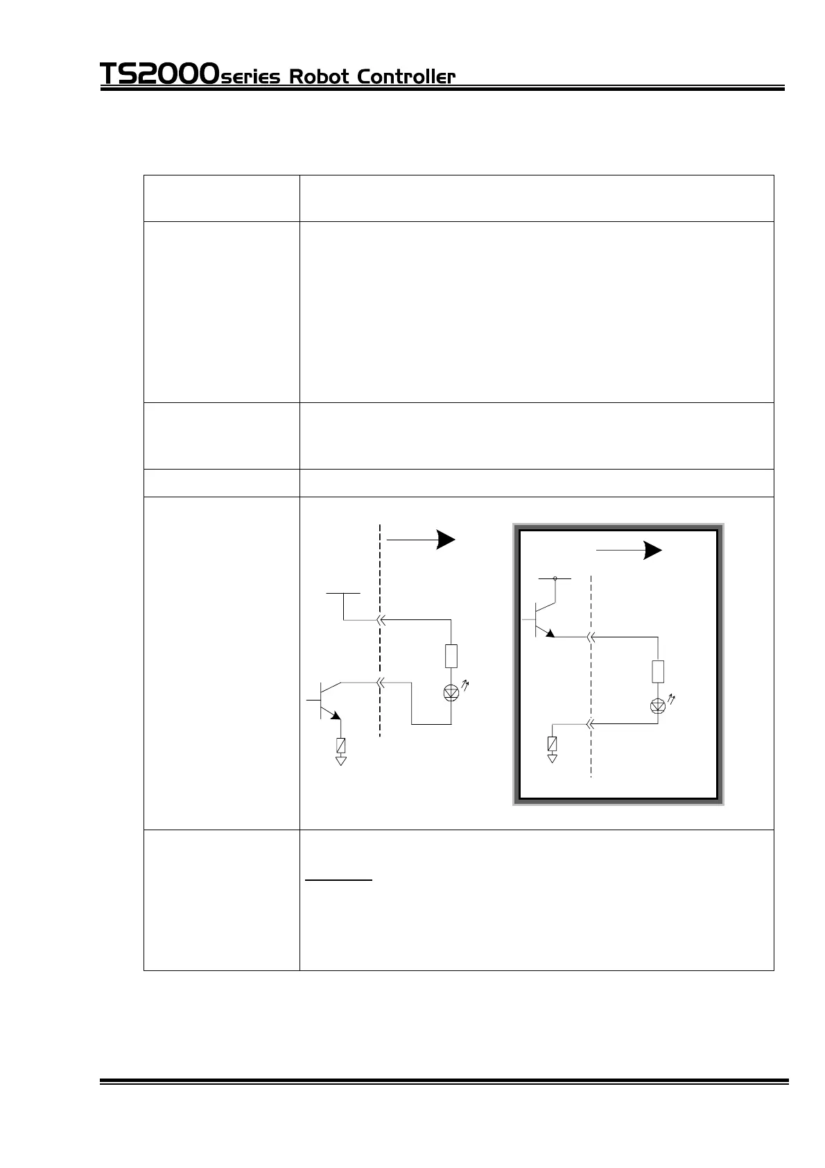
Output type Transistor output
Output circuit
structure
User side
P24V
●
P24G
[ Sink type ("-" common) ]
User side
P24V
P24G
[ Source Type ("+ " common) ]
●
Electric rating Rated voltage: DC24 V Rated current: 100 mA (max.)
Caution:
If the current which exceeds the rated output current is
supplied, the output device may be damaged or the printed
board may be burnt. To avoid this, be sure to use within the
rated output current.
STE 71367
– 62 –
 Loading...


