32 Ethernet module User’s Manual
Chapter 4 Preparing for Operation (Software)
4
4.1 Module Setup Flowchart (Software)
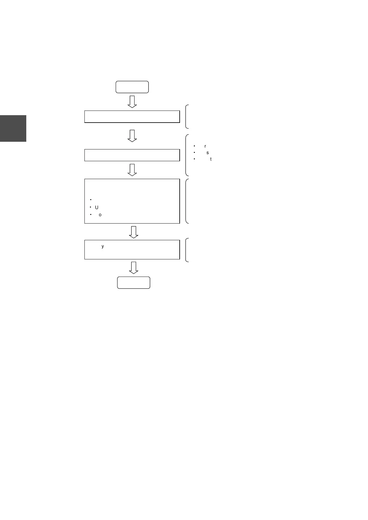
The following figure shows the flowchart for EN311 setup.
Figure 4-1 EN311 Setup Flowchart (Software)
Start
Register the EN311 with the controller
Reset the EN311
Set the EN311 parameters from the
controller
・
Local IP address
・
UDP port number for message transfer
・
Router IP address
Register the EN311 with the S controller using the V Series
Engineering Tool.
For details, see section 4.2, "Registering the EN311."
There are three ways to reset the EN311:
・
Turn on the controller power.
・
Press the reset switch.
・
Reset by a user program.
For details, see section 4.5, "Resetting the EN311 ."
The EN311 parameters required for network transmission
are set up by a user program running on the S controller. In
this state, the system can handle remote station verification
requests. In this state, the system can also respond to
existence verification requests from other stations. See
section 7.3, "Remote Station Verification Request."
The EN311 operating mode is set by user programs running
on the controller. For details, see section 4.8, "Operating
Mode Control Requests."
Specify the EN311 operating mode from
the controller
End
In this state, the PC link/computer link protocol transmission
slave station functions are operating.
 Loading...