Unified Controller Vm series TC-net 100 (TNB) Module Instruction Manual
47
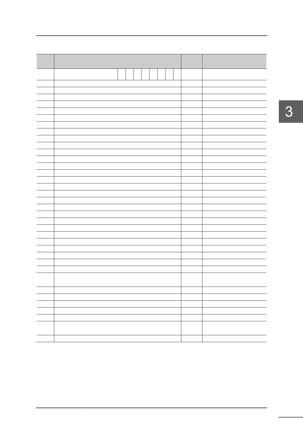
Table 3-8 Information configuration of RAS information block
Word
No.
F 8 7 0
Update
cycle
Remark
0 Module Type (0x4)
0 000
1
00
11s
Install information of the target
controller(*1)
1 TNB healthy counter 0.1s YNB21/22 healthy counter
2 Slot 0 healthy counter 0.1s CPU No1 PLC
3 Slot 1 healthy counter 0.1s CPU No2 PLC
4 Slot 2 healthy counter 0.1s CPU No3 PLC
5 Slot 3 healthy counter 0.1s CPU No4 PLC
6 Slot 4 healthy counter 0.1s Linux or Windows
7 Slot 5 healthy counter 0.1s Reserved
8 Slot 6 healthy counter 0.1s Reserved
9 Slot 7 healthy counter 0.1s Reserved
10 Reserved
-
11 Reserved
-
12 Reserved
-
13 Reserved
-
14 Reserved
-
15 Reserved
-
16 Controller type 1s CPU No1 PLC SW0
17 Controller subtype 1s CPU No1 PLC SW1
18 Phase/Mode 0.1s CPU No1 PLC SW14
19 Head alarm 0.1s CPU No1 PLC SW256
20 Reserved
-
21 Reserved
-
22 Controller type 1s CPU No2 PLC SW0
23 Controller subtype 1s CPU No2 PLC SW1
24 Phase/Mode 0.1s CPU No2 PLC SW14
25 Head alarm 0.1s CPU No2 PLC SW256
26 Reserved
-
27 Reserved
-
28 Controller type 1s CPU No3 PLC SW0
・
・
・
・
・
・
・
・
・
40 Controller type 1s Linux or Windows
41 Controller subtype 1s
42 Phase/Mode 0.1s
43 Head alarm 0.1s
44 Reserved
-
・
・
・
・
・
・
・
・
・
63 Reserved
-
(*1) Install information of the target controller corresponds to 1 - Install, 0 - non-install.
0 bit - 0 slot (CPU No1 PLC), 1 bit - 1 slot (CPU No2 PLC), 2 bit - 2 slot (CPU No3 PLC),
3 bit - 3 slot (CPU No4PLC), 4bits - 4 slots (Linux or Windows), bit map meaning.
For Controller type, controller subtype, phase/mode, head alarm, refer to the
function manuals of controller. "Unified Controller Vm series Controller typeS
PLC CPU Functional Manual" (6F8C1652)
 Loading...


