Do you have a question about the TOTALINE P474-0130 and is the answer not in the manual?
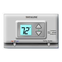
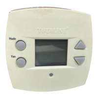
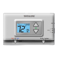
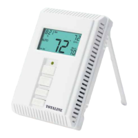
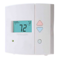
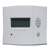
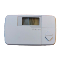
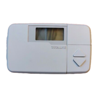
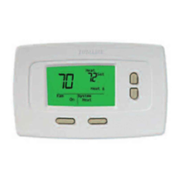
Identifies the key components and buttons on the thermostat, including the display, mode switch, and fan switch.
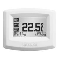
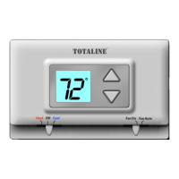
Explains the thermostat's digital display, showing current room temperature and set temperature indication.
Details how to operate the thermostat for heating, cooling, and fan functions using the mode and fan switches.
Critical safety precautions and warnings for installing and operating the thermostat, including battery replacement.
Outlines necessary tools and initial steps before thermostat installation, including safety checks and power disconnection.
Step-by-step guide for safely removing the old thermostat and preparing for the new installation.
Instructions for opening the thermostat housing and replacing batteries, emphasizing timely replacement for optimal operation.
Details on how to correctly position batteries and when they need to be replaced, referencing low battery indicators.
Guidance on connecting wires to the new thermostat, including a chart for matching old and new terminal designations.
Illustrates typical wiring configurations for 4-wire, 1-stage cooling and gas/electric heat systems.
Wiring diagram for 4-wire, 1-stage heat pump systems with an 'O' reversing valve, no auxiliary heat.
Wiring diagram for 4-wire, 1-stage heat pump systems with a 'B' reversing valve, no auxiliary heat.
Wiring diagram for 3-wire, 1-stage gas or electric heat units with a separately controlled fan.
Wiring diagram for 2-wire, 1-stage gas or millivolt units.
Wiring diagram for 3-wire, 1-stage residential electric cooling units.
Explains how to set jumpers for specific HVAC system types, like electric heat or heat pumps, for correct operation.
Guide for testing the heating, cooling, and fan functions after installation to ensure proper system operation.
Addresses common thermostat issues, such as difficult slide switches or air conditioning not turning on, with causes and remedies.
Provides solutions for heating not turning on, linking symptoms to setpoint, mode switch, or battery issues.
Details the one-year limited warranty, exclusions, limitations, and conditions of coverage for the thermostat product.
| Stages | 1 Heat/1 Cool |
|---|---|
| Display | Digital |
| Voltage | 24V |
| Backlight | Yes |
| Programmable | Yes |
| Hold Function | Yes |
| Filter Change Alert | Yes |
| System Switch | Heat/Cool/Off |
| Fan Control | Auto/On |
| Power Source | Battery |
| Battery | 2 AA Batteries |
| Programmability | 7-Day Programmable |