tousek / EN_ST-61A_08 / 25. 03. 2020 - 7 -
2.2 Connections and adjustments Trac light control unit STA 11
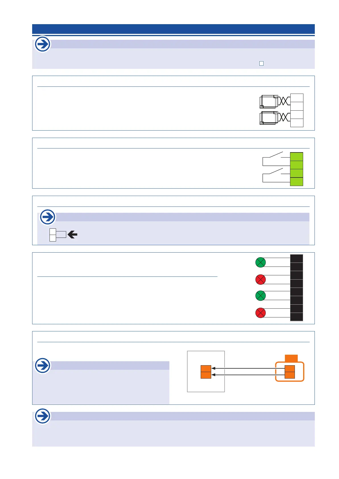
Induction loops
• For the use of induction loops (for Green/Opening command) the I-loop slot (ISD) of the trac light board
STA 11 has to be equipped with an optional avalaible I-loop detector ISD 6 (2-channels). (
page 9)
Adjustments
• The functions of the trac light control is determined by the settings of the connected operator control board.
These relate to the duration of the green phase and the clearance time, the trac light at the closed door position
(whether or continuous red) and the trac light logic (both sides / one side green).
9/1
9/2
9/3
9/4
induction loop
outside
induction loop
inside
Induction loop input (outside: term. 9/1+9/2, inside: term.9/3+9/4) Connections
• For the connection of induction loops to give an impulse to the green request.
• With the 2-channel I-loop detector ISD 6 both loops (inside/outside) can be
evaluated.
STA 11
Impulse switch (outside: term. 38/30, inside: term. 32/30) Connections
• For the connection of impulse switches on the inside and outside to give
an impulse for the green request. The impulse is also possible via an
optional, plug-in radio receiver.
• The green switching for one or both sides is dependent on the adjustment
of the trac light logic of the operator control board.
38
30
32
30
impulse switch
outside
impulse switch
inside
STA 11
Trac light outputs
outside: GREEN: term. 97/6, RED: term. 99/6
inside: GREEN: term. 96/6, RED: term. 98/6)
Connections
• on the described terminals Red/Green trac lights (230V max. 60W) can be
connected for inside and outside location.
97
6
99
6
96
6
98
6
GREEN
outside
RED
outside
GREEN
inside
RED
inside
230V max. 60W
STA 11
B
operator control unit
Bus
High
Bus
Low
88
89
88
89
STA 11
ST 61A
Important
• Max. cable length between automation and trac
light control is 25m.
• Cable type e.g.: shielded control cable
YSLY 2 x 1mm
2
oder gleichwertig.
Connection trac light board with operator control board (term. 88/89) Connections
• Via the bus system (see pic.) the trac light control board
is connected with the operator control board.
Important
60
61
STA 11
With the control unit ST 61A no limit switch connection at the trac control unit
STA 11 is necessary, instead the terminals 60/61 must be wire bridged!
Limit switch input (term. 60/61) Connections