6.4 Application Example for Protocol VLAN
Network Requirements
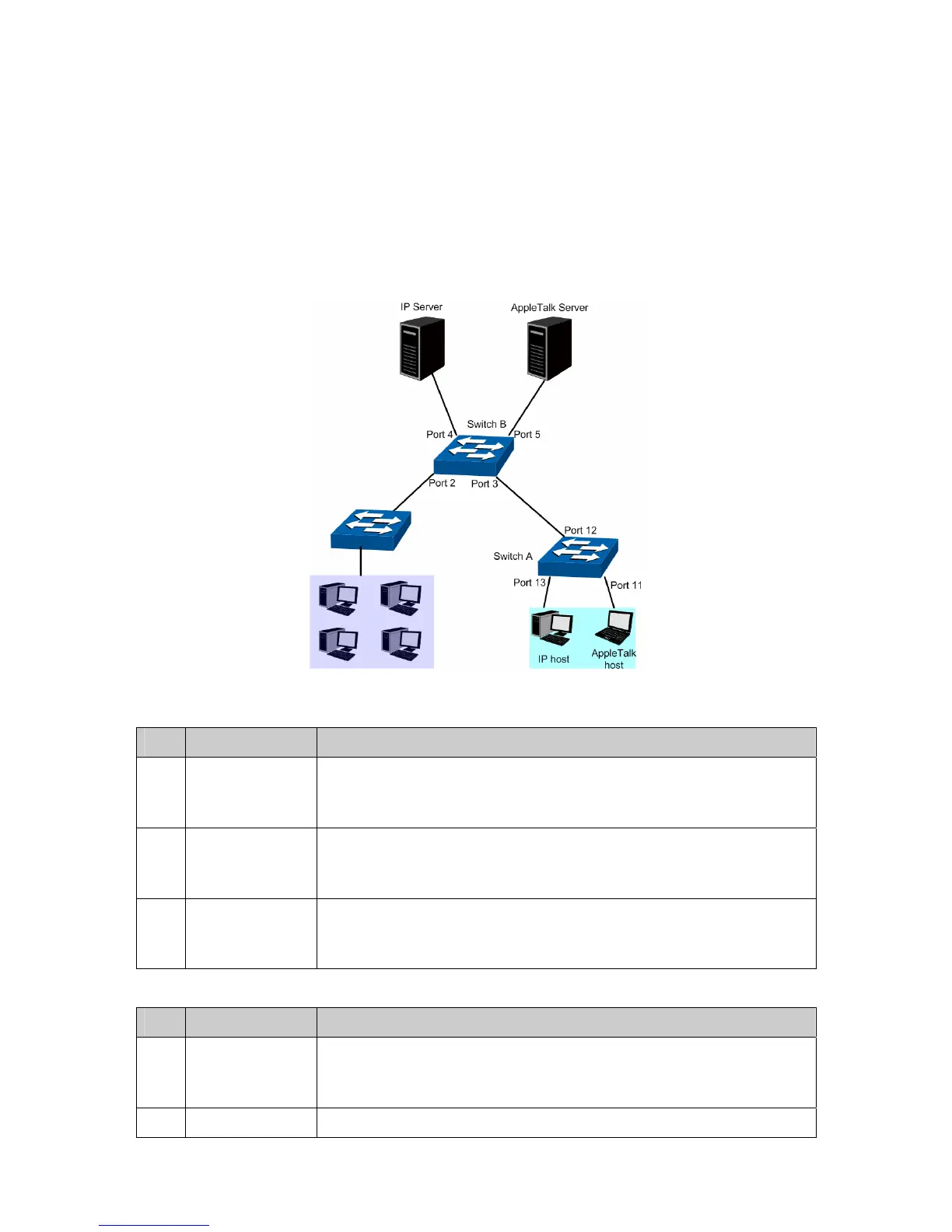
Department A is connected to the company LAN via Port12 of Switch A;
Department A has IP host and AppleTalk host;
IP host, in VLAN10, is served by IP server while AppleTalk host is served by AppleTalk server;
Switch B is connected to IP server and AppleTalk server.
Network Diagram
Configuration Procedure
Configure Switch A
Step Operation Description
1 Configure the
Link Type of the
ports
Required. On VLAN→802.1Q VLAN→Port Config page, configure the
link type of Port 11 and Port 13 as ACCESS, and configure the link type
of Port 12 as GENERAL.
2 Create VLAN10 Required. On VLAN→802.1Q VLAN→VLAN Config page, create a
VLAN with its VLANID as 10, owning Port 12 and Port 13, and
configure the egress rule of Port 12 as Untag.
3 Create VLAN20 Required. On VLAN→802.1Q VLAN→VLAN Config page, create a
VLAN with its VLANID as 20, owning Port 11 and Port 12, and configure
the egress rule of Port 12 as Untag.
Configure Switch B
Step Operation Description
1 Configure the
Link Type of the
ports
Required. On VLAN→802.1Q VLAN→Port Config page, configure the
link type of Port 4 and Port 5 as ACCESS, and configure the link type of
Port 3 as GENERAL.
2 Create VLAN10 Required. On VLAN→802.1Q VLAN→VLAN Config page, create a
64