User Guide 54
Configuring VLAN Configuration Example for 802.1Q VLAN
5.3 Network Topology
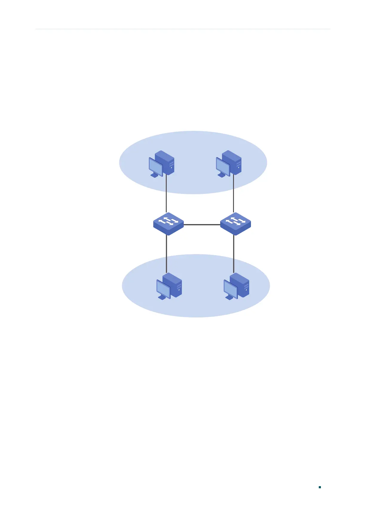
The figure below shows the network topology. Host A1 and Host A2 are in Department
A, while Host B1 and Host B2 are in Department B. Switch A and Switch B are located in
two different places. Host A1 and Host B1 are connected to port 2 and port 3 on SwitchA
respectively, while Host A2 and Host B2 are connected to port 2 and port 3 on Switch B
respectively. Port 4 on Switch A is connected to port 4 on Switch B.
Figure 5-1 Network Topology
VLAN 2
VLAN 3
Host A1 Host A2
Host B1
Host B2
Switch A
Switch B
Port 2
Port 3
Port 4
Port 2
Port 3
Port 4