16
L2 Managed Switch
1
2
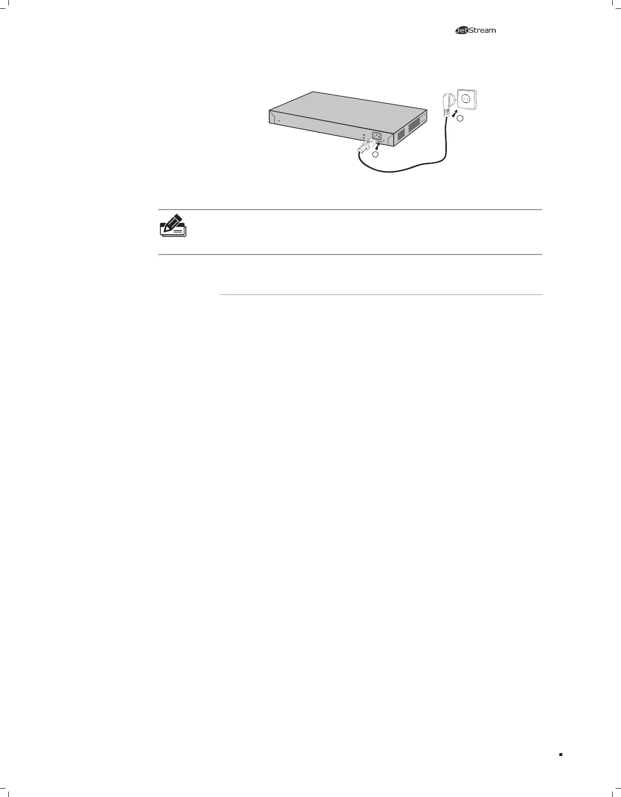
Figure 4-5 Connecting to Power Supply
Note: The gure is to illustrate the application and principle. The power cord you get
from the package and the socket in your situation will comply with the regulation in
your country, so they may differ from the gure above.
4.6 Initialization
After the device is powered on, it begins the Power-On Self-Test. A series of tests
run automatically to ensure the device functions properly. During this time, its LED
indicators will respond in the following order:
■
The PWR LED indicator will light on all the time.The SYS LED and the LED indicators
of all the ports keep off.
■
After over ten seconds, the SYS LED and LED indicators of all the ports will flash
momentarily and then turn off.
■
Several seconds later, the SYS LED indicator will flash, which represents a successful
initialization.
Connection
 Loading...