Page 2-2 Installation Instructions TQG191-IM
Rev 0: 28 Feb 2019
2.3 PRE-INSTALLATION CHECKLIST
Before beginning the installation, ensure that the aircraft and all associated equipment meet the
requirements of the AML STC and government regulations. This pre-Installation Checklist,
Table 2-1, should be completed before any aircraft or equipment modification begins.
Table 2-1: Pre-Installation Checklist
An Electrical Load Analysis has been performed to ensure that the electrical
system is sufficient for the installation
Is there a compatible GPS installed in aircraft?
All peripheral equipment (GPS Source, antennas, coax, etc.) are approved
under STC or a Field Approval
There is adequate space, structural integrity and ventilation (if required) for
all installed equipment
There is an acceptable L-Band antenna location on bottom of aircraft
All equipment has been unpacked and inspected for damage.
Equipment received has been compared to packing list(s)
2.4 SUPPLIED EQUIPMENT
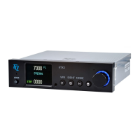
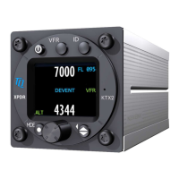
The equipment supplied for a typical KTX2 installation is listed in Table 2-2.
Table 2-2: Supplied Equipment
2.5 EQUIPMENT REQUIRED BUT NOT SUPPLIED
Use Table 2-3 to identify equipment required for installation, calibration and testing of the KTX2.
Equivalent tools, equipment and hardware may be used provided they meet the standards
described in FAA Advisory Circulars (AC) 43.13-1B, 43.13-2B, or later revisions of these
documents.
Table 2-3: Equipment List – KTX2
The installer supplies all system wires and cables.
Mating Connector (P1)
•
Wires are 22 AWG (signal) or 20 AWG as noted on interconnect wiring
diagram in section 2. Use M22759 or equivalent wire for installation.
•
wiring diagram.
Antenna Cables
•
L-Band Antenna
Require RG400 or equivalent coaxial cable. For the L-Band antenna the
attenuation must not exceed 1.5 dB per cable (including the connectors).
Refer to Table 2-5.
•
 Loading...