Do you have a question about the TR-Electronic C 65 Series and is the answer not in the manual?
Assembly instructions for the rotary encoder.
Operating instructions for the rotary encoder.
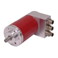
Technical specifications and data for the CEV65M-10323.
Fundamental safety guidelines and symbol definitions.
Explanation of how absolute and incremental encoders function.
Detailed steps and schematics for mounting the encoder.
Defines the applicability of the assembly instructions to specific encoder models.
Lists related documentation essential for system setup and use.
Defines safety symbols (Warning, Caution, Notice) and their meanings.
Operator responsibilities regarding EMC directives and system compliance before operation.
Identifies potential dangers and emphasizes correct usage and maintenance.
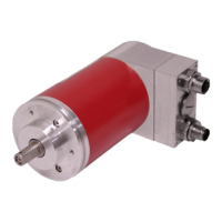
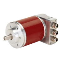
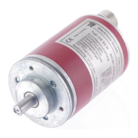
Describes methods for mounting encoders with solid shafts using couplings.
Details flange mounting procedure using centering collars and screws.
Explains mounting via a clamping flange and centering collar.
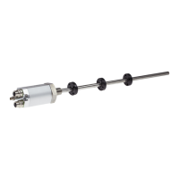
Describes mounting methods for encoders with blind shafts.
Details mounting using a torque holder to prevent shaft rotation.
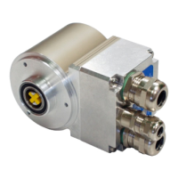
Describes encoders with integrated coupling for direct shaft connection.
Explains the advantages and mounting of integrated coupling units.
Specifies the measuring system models covered by this user manual.
Lists relevant industry standards and guidelines for PROFINET and SSI.
Provides definitions for technical terms and abbreviations used.
Overview of PROFINET as an Industrial Ethernet standard for automation.
Details the PROFINET IO device model and communication structure.
Explains PROFINET's real-time communication classes (RT, IRT).
Describes PROFINET network topology and cabling requirements.
Details the SSI interface connection and cable specifications.
Provides pin assignments for PROFINET and supply connections.
Specifies connections for PROFINET ports and power supply.
Details pin assignments for cam outputs and preset inputs.
Shows pin assignments for the SSI interface.
Information on GSDML file updates and structural changes for PROFINET configuration.
Explains the role and format of the GSDML file for PROFINET Plug-and-Play.
Details the Vendor-ID and Device-ID for PROFINET IO device identification.
Describes the PROFINET IO communication sequence and data transfer.
Procedure for assigning IP addresses, MAC addresses, and device names.
Explanation of the MAC address structure and its function.
Details the structure and assignment of IP addresses for network communication.
Explains the function of subnet masks in network addressing.
Provides an overview of available configurations and their features.
Configuration details for encoders with ≤ 12 bit resolution and standard functions.
Configuration for ≤ 15 bit resolution, gearbox functions, and extended ranges.
Configuration for encoders with optional SSI interface.
Details on operating parameters like rotational direction and SSI interface codes.
Setting the direction of position value increase (clockwise/counter-clockwise).
Selection of SSI output code format (Binary or Gray).
Procedure for adjusting the encoder's position value via PROFINET.
Interpreting the status of diagnostic LEDs on the encoder.
Handling PROFINET diagnostic alarms for error localization.
Details on channel-specific diagnostic error codes and remedies.
Lists manufacturer-specific diagnostic error codes and their corresponding remedies.
| Brand | TR-Electronic |
|---|---|
| Model | C 65 Series |
| Category | Media Converter |
| Language | English |