10
system voltage in the left column, and the distance from your power source (feet/meters) to
the C40 (or the distance from the C40 to your load) on the same line, then read the wire
size required at the top of the column. Don’t use wire smaller than #8 gauge.
The wiring, overcurrent protection devices (fuses and circuit breakers) and installation
methods used must conform to all local electrical codes requirements.
Wiring should be protected from physical damage with conduit or a strain relief clamp. You
should pull the temperature sensor cable through the conduit first as the connector may not
fit if other wires have been pulled first.
As a minimum, a 60-amp DC rated current limiting fuse in an appropriate fuse holder or
disconnect switch should be provided near the battery for protection from short circuits.
Local electrical codes should be consulted for wire sizing and any additional installation
requirements. The use of breakers or fuses above 60 amps is not recommended. Use
Trace part number CD60DC available from your Trace dealer.
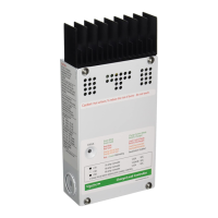
Photovoltaic arrays generate current whenever light strikes the surface of the array. Before
connecting the C40, cover the array to prevent any current from being generated. Remove
one or more of the knockout plugs on the C40’s case and feed the connecting wires
through it. Connect the PV array’s positive output to the terminal marked PV POS/LOAD at
the bottom of C40’s circuit board. Connect the negative output to the terminal marked PV
NEG. Tighten the lugs to 12 ft/lbs (17.86 Kg/m)
Connect the battery positive cable to the terminal marked BAT POS on the bottom of the
C40’s circuit board. Connect the negative battery cable to the terminal marked BAT NEG
on the C40’s circuit board. Secure the cabling with strain reliefs after allowing a little slack
inside the case to prevent damage to the C40’s circuit board.
When using the C40 as a diversion or DC load controller, the DC load needs to be
connected to the terminals marked as PV POS/LOAD and PV NEG on the C40. The two
negative terminals are common and can be reversed or wired with a single conductor to a
more convenient location such as a DC load center negative bus.
Connect your DC current source (PV, wind, hydro, etc.) directly to a battery, then connect
an appropriately-sized cable from the positive battery terminal to the C40 terminal marked
BAT POS. Connect a cable from the negative battery terminal to the terminal marked BAT
NEG on the C40’s circuit board. Connect a cable from the C40’s terminal marked PV
POS/LOAD to the positive terminal of your DC Diversion load. Connect a cable from the
terminal marked PV NEG on the C40 to the negative terminal of your DC Diversion load.
Tighten the terminal lugs to 12 ft/lbs (17.86 Kg/m). Allow a little slack on the cables within
the C40 and secure the wiring with strain reliefs.
PV Charge Control Mode Cabling
Diversion Control Mode Cabling
Copyright Trace Engineering Co. Inc. Tel (360) 435-8826 Part Number 2680 Rev. C
5916 195 Street, NE Fax (360) 435-2229 November 4, 1998
Arlington, WA 98223 USA www.traceengineering.com Page
th
C40
VOLTAGE
12vdc
24vdc
48vdc
8AWG
5.6/1.7m
11.1/3.38m
22.2/6.77m
6AWG
8.8/2.68m
17.6/5.36m
35.2/10.72m
4AWG
14/4.26m
28/8.53m
56/17.06m
3AWG
17.7/5.38m
35.4/10.79m
70.8/21.58m
2AWG
22.4/6.83m
44.8/13.66m
89.6/27.31m
Maximum One-Way Wire Distance in Feet/Meters
(40 Amps with 3% Voltage Drop)