14
Temperature Compensation
Setting LVR and LVD (Load Control Mode)
Setting HVD (Diversion Control Mode)
If a temperature compensation sensor is installed, the charge or diversion control process
will be automatically adjusted for the battery temperature. Set BULK and FLOAT voltage
for a battery at normal room temperature (23 -27°C/74 -80°F). Actual voltage may vary
above or below these settings due to adjustment for battery temperature.
If no temperature compensation sensor is installed and the batteries will be operating in
very hot or very cold conditions, adjust the BULK and FLOAT settings to allow for the
battery temperature. The recommended adjustments can be found in the table below. The
setting should be lowered for ambiant temperatures above 80 F/27 C and raised for
ambiant temperature below 75 F/23 C. If significant seasonal variations are common, you
will have to change the settings several times a year to prevent battery damage and ensure
proper operation.
Do not compensate the settings when using the C40 as a DC Load Controller.
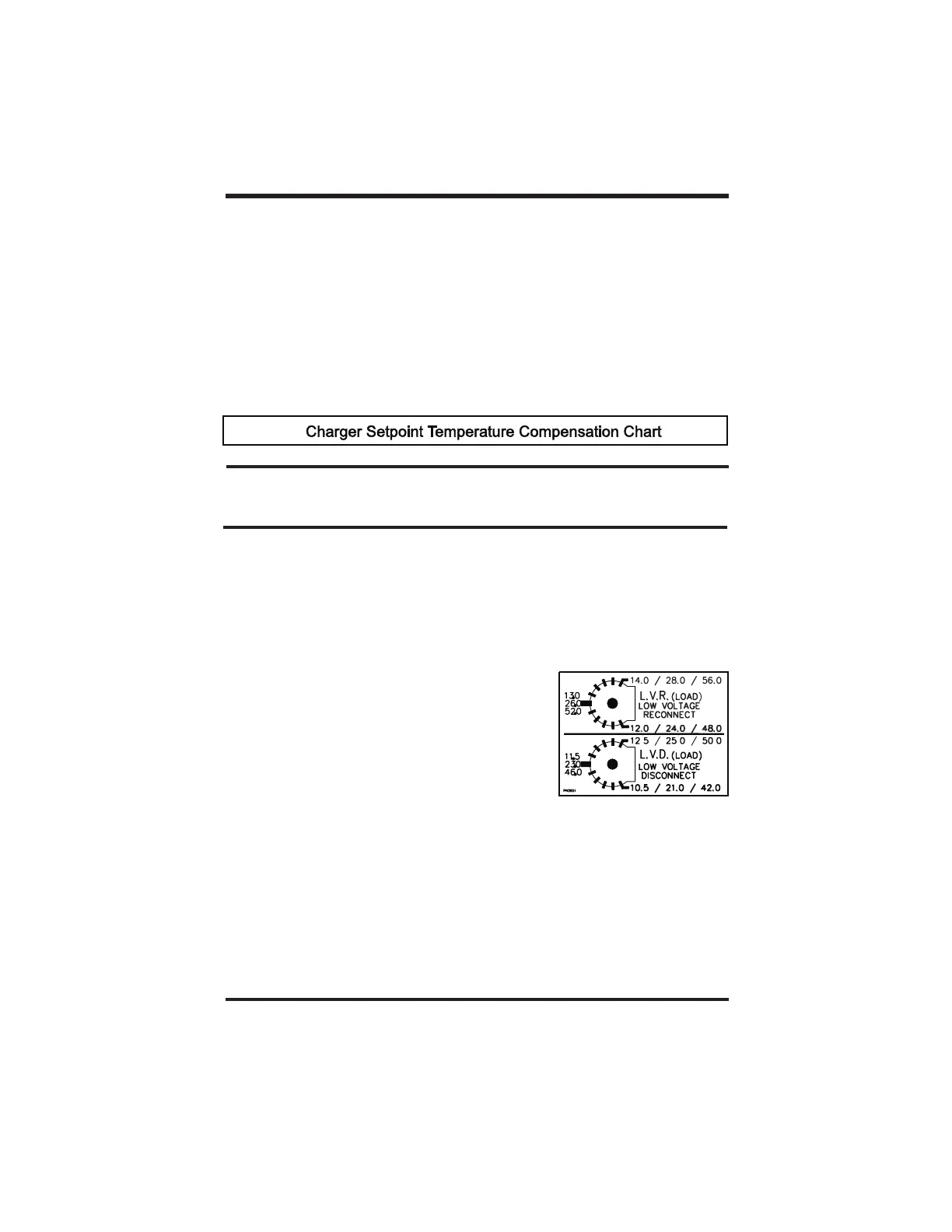
You can change the low voltage disconnect (LVD) and low voltage reconnect (LVR) settings
using the same potentiometers described above. When the C40 is in DC Load Control
mode, the pots scale calibration is altered. For 12-volt application subtract two volts from
the scale shown on the circuit board for the LVR setting (Bulk setting when in Charge
Control mode) and subtract two volts from the scale shown for the LVD setting (Float setting
in Charge Control mode). Subtract four volts for a 24-volt application, and eight volts for a
48-volt application . The C40 comes with a two-part decal
that can be placed over the pots (after removing the
knobs) that shows the correct scales for DC Load Control
mode. The decal can be found inside the C40 chassis at
the bottom.
MANUAL reconnect of the loads is allowed if voltage has
not exceeded the LVR setting. To reconnect the loads,
press the reset button on the right side of the C40. If the
voltage is below the LVR level, the DC load can be
reconnected for an approximately 10 minute “grace”
period. Multiple “grace” periods are allowed, but the
duration of the ‘grace’ period will vary with battery voltage. The EQUALIZE jumper allows
the C40 to be set for AUTO reconnect of the DC load when the voltage exceeds the LVR
setting.
When the C40 is configured for Diversion Control mode, you can set the voltage at which
the unit begins diverting current (high voltage diversion). The unit will continue diverting
excess current to the diversion load until the source voltage falls to the HVD (Bulk) setting.
°°
°°
Note: The LED will light red in Load Control mode; never in Charge or Diversion
mode.
only
Copyright Trace Engineering Co. Inc. Tel (360) 435-8826 Part Number 2680 Rev. C
5916 195 Street, NE Fax (360) 435-2229 November 4, 1998
Arlington, WA 98223 USA www.traceengineering.com Page
th
Charger Setpoint Temperature Compensation ChartCharger Setpoint Temperature Compensation Chart
Battery Type System Voltage
12 VOLT 24 VOLT 48 VOLT
Lead Acid (6 cells) .030 Volts/ C .060 Volts/ C .120Volts/ C
Nicad (10 cells) .020 Volts/ C .040 Volts /C .080 Volts/ C
°°°
°° °