batteries reduce the maintenance requirements for the system and are good for remote
applications. They are much more sensitive to the charging process and can be ruined in
as little as a day of overcharging.
The Trace C40 is compatible with(NiCad (nickel-cadmium) and (NiFe)(nickel-iron or
alkaline) type batteries, which must be charged to a higher voltage level to achieve a full
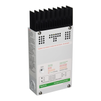
charge. To use the C40 with NiCad batteries, remove the resistor labeled “R46” in the
middle of the C40 circuit board by cutting it. This adds two volts to the printed scale on the
circuit board around the BULK and FLOAT potentiometers. When NiCad mode is selected,
the equalization process is disabled.
Adjust the BULK Charge Voltage to the setting recommended by the battery manufacturer.
Add 2 volts to the scale shown when making the adjustment. FLOAT voltage settings for
NiCad/NiFe batteries should also be set to the battery manufacturer’s recommendations.
Add 2 volts to the scale when making the adjustment.
In all applications the BULK voltage setting should be adjusted to a level below the
maximum operating voltage of the DC loads. This may be as low as 15 volts for some
types of electronic loads. Under-charging may occur in this instance, but DC equipment will
be protected. Check with the manufacturers of the DC equipment being powered for its
maximum DC input voltage tolerance. If equalization is expected to occur, than the DC
equipment being used must tolerate the voltages which will occur during the equalization
process.
Batteries are the fuel tank of the system. The larger the batteries, the longer the system
can operate before recharging is necessary. An undersized battery bank results in short
battery life and disappointing system performance. To determine the proper battery bank
size, compute the number of amp-hours that will be used between charging cycles. Once
the required amp-hours are known, size the batteries at approximately twice this amount.
Doubling the expected amp-hour usage ensures that the batteries will not be overly
discharged and will extend battery life. The critical formula is Watts = Volts X Amps. Divide
the wattage of the load by the battery voltage to determine the amperage the load will draw
from the batteries. Multiply the amperage times the hours of operation and the result is,
reasonably enough, amp-hours.
The job of the charge controller
is to see that a battery bank is charged in a controlled manner. Also, protection against
over discharge and overcharging is provided by disconnecting the charging source(s) from
the battery should one of these conditions occur.
NiCad and NiFe Batteries
Battery Sizing
Diversion Loads
Anyone dealing with solar, wind, or hydro power generation systems knows that a critical
component in these systems is the charge/load controller(s).
A load controller is generally designed to remove a load or loads from the system when an
over discharge or overload situation occurs.
A diversion load controller is designed to monitor battery state, and when the battery is full,
divert the power coming out of the source (Solar, wind, or hydro generator) to a load which
will utilize the excess power. Usually a water heater or some other type of heating element
is present for this purpose.
Systems utilizing solar arrays do not have a requirement for diversion loads since a solar
module can be open circuited without damage. However, even with a solar based system it
is desirable to use excess power to operate DC loads. On the other side of the equation,
when a wind or hydro generator is operating, the diversion load prevents over speeding and
self destruction. Unload the system by suddenly removing the load and the generator will
over speed and potentially fail. The only way to safely deal with this situation is to either
stop the generator, or allow its power output to continue, but divert it away from the
batteries to prevent overcharging. This is the duty of a diversion load controller.
Copyright Trace Engineering Co. Inc. Tel (360) 435-8826 Part Number 2680 Rev. C
5916 195 Street, NE Fax (360) 435-2229 November 4, 1998
Arlington, WA 98223 USA www.traceengineering.com Page
th
19