Load Control Indications
Equalization Mode Indication
Error Mode Indication
Mounting
Solid Red -
Blinking Red
Alternating Red and Green -
Caution: It is in your best interests to install the C40 in a dry, protected location away
from sources of high temperature, moisture, and vibration. Exposure to saltwater is
particularly destructive. Corrosion of the circuit board is not covered by the
warranty. If you wouldn’t put your television there, don’t put the C40 there.
indicates that the controller is in the DC Load Control mode and the battery
voltage has reached the Low Voltage Disconnect (LVD) setting. After a 10 minute delay,
DC loads will be disconnected unless the user reduces the loads to a point that the battery
voltage exceeds the LVD setting.
- As battery voltage approaches the LVD setting, the LED will blink red
several times (up to 5) and then pause. This provides an indication of battery condition.
Slow Blinking Orange - indicates that the C40 is in the DC Load Control mode and has
disconnected the loads due to reaching the LVD setting. The user can press the reset
switch for a maximum10 minute “grace” period, or can wait until the voltage rises above the
Low Voltage Reconnect (LVR) setting to allow an automatic reset to occur.
indicates that the C40 is in equalize mode. It will
automatically stop the equalization process after accumulating two hours of operation at a
voltage above the BULK setting. The user can stop the equalization process at any time by
pressing the reset switch until the status LED stops alternating red and green.
Fast Blinking Orange - indicates that the C40 has detected a short circuit or an over-
temperature condition and has disconnected the loads. The C40 will try to automatically
restart the loads after a 10 minute delay. If the C40 will not restart, turn off all loads and
press the reset switch. If the C40 then restarts, the loads may be too large. A delay up to
five seconds may occur before the C40 attempts to restart after pressing the reset switch.
The C40 controller is a state-of-the-art precision electronic instrument. Installation,
environment, mounting, and wiring must be accomplished in accordance with applicable
local and national electrical codes. The instructions that follow are applicable to the typical
installation. For special applications, consult a qualified electrician or your Trace dealer.
Installation procedures will vary according to your specific application.
The C40 is designed for indoor mounting. Care should be taken in selecting a location and
when mounting the enclosure. Avoid mounting the C40 in direct sunlight in order to reduce
heating of the enclosure and subsequent high operating temperatures. The enclosure
should be mounted vertically on a wall.
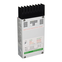
Mounting and enclosure dimensions are shown in the adjacent diagram. Remove the
faceplate on the C40 and locate the upper two screw locations on the wall. The back of the
enclosure is provided with key-holes for mounting. Leave the screw heads backed out
approximately 1/4 inch (6 mm). Place the C40 onto the screws and pull it down into the
keyhole slots. Then insert the two lower screws to lock the enclosure onto the wall.
Provide either strain-relief clamps or conduit to prevent damage to the circuit board and
terminal block from pulling on the wires. The cover should be replaced and retained with
the screws provided (#10-32 x 3/8” SMS).
In severe environments, additional consideration should be taken to minimize exposure to
wet environments. The use of conformal-coated circuit boards, plated terminals, powder
coated metal components, and stainless steel fasteners improves tolerance to hostile
environments.
Installation
8
Copyright Trace Engineering Co. Inc. Tel (360) 435-8826 Part Number 2680 Rev. C
5916 195 Street, NE Fax (360) 435-2229 November 4, 1998
Arlington, WA 98223 USA www.traceengineering.com Page
th