5
diversion load to redirect the excess power generated instead of allowing it to flow into the
battery. This prevents damage to the charging source from an over-speed condition which
could occur if the charging source is suddenly disconnected from all loads - as series relay
regulators do. Consult your dealer for load and regulator size recommendations.
When the C40 operates as a diversion regulator, it provides three-stage regulation of
battery voltage, with temperature compensation and automatic or manual equalization.
See the section for more information on this process.
Diversion mode requires a separate load “dump” to regulate the battery. This load must be
able to absorb more power than the charging source is able to produce at its peak output,
or the DC voltage will become unregulated. The dump load must be available for the
diversion of power at all times. Resistive-type heating elements are the best diversion
loads. Special direct current water heating elements are available. Light bulbs and motors
are not recommended as diversion loads because they are unreliable.
When used in diversion mode, ensure that the operating mode jumpers are on the charge
control pins. See the section of this booklet.
Current draw of the diversion load is very important. Problems may arise from operating
with a load that is too small or too large. A diversion load that is too small will not be able to
absorb all the excess power from the current source once the batteries are full.
Diversion loads in excess of 63 amps are capable of absorbing more power than the C40 is
designed to handle, resulting in an over-current shut down. During this time, the unit will
not regulate electrical flow in the system, and battery damage may result.
A diversion load that draws about 50 amps when connected to the battery is usually
suitable for use with the C40. The load should be sized about 25% larger than the charging
source’s maximum output capability.
The C40 can also operate as a 40-amp load control (also called a low voltage disconnect)
to manage the discharging of the battery. A load controller prevents damage to the battery
from over-discharge during periods of poor weather or excessive loads.
When used in load control mode, ensure that the operating mode jumpers are on the load
control pins. See section of this booklet.
The controller delays disconnecting the DC loads for 10 minutes after the voltage drops
below the low voltage disconnect (LVD) setting. Loads are either automatically or manually
reconnected when battery voltage exceeds the low-voltage reconnect (LVR) setting for 10
minutes. The EQUALIZE jumper determines manual or automatic reconnect when the C40
is used as a load controller.
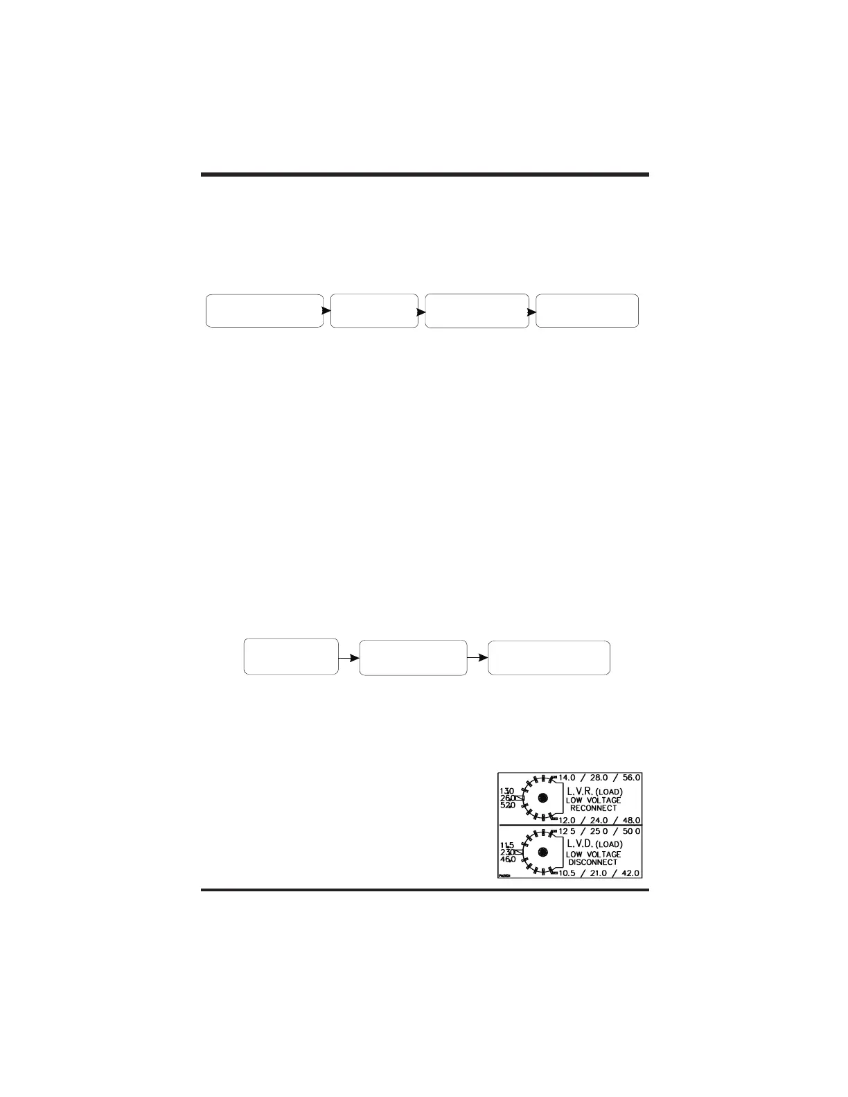
When used as a DC load controller, the settings of the
LVR and LVD are controlled by two rotary knobs on the
circuit board. The scale on the adjustment pots differ
from the scale used for other functions. A decal with
the corrected adjustment scale is included with the C40
and shown at right. Place this scale over the pots
when using the C40 as a load controller. Do not
temperature-compensate these settings. Do not install
the optional battery temperature compensation sensor.
Three-stage Battery Charging
User Configuration Options
Configuring the C40
DC Load Control Mode
Copyright Trace Engineering Co. Inc. Tel (360) 435-8826 Part Number 2680 Rev. C
5916 195 Street, NE Fax (360) 435-2229 November 4, 1998
Arlington, WA 98223 USA www.traceengineering.com Page
th
DC LOADDC LOAD
Battery
C40
controller
C40
controller
Battery
C40
controller
C40
controller
Diversion
‘dump’ load
Diversion
‘dump’
load
PV, HYDRO,
or WIND
PV, HYDRO,
or
WIND