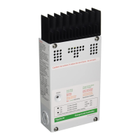
Install the BTS on the side of the battery below the
electrolyte level. It is best to place the
sensor between batteries and place the batteries in an
insulated box to reduce the influence of the ambient
temperature outside the battery enclosure. Ventilate the
battery box at the highest point to prevent hydrogen
accumulation.
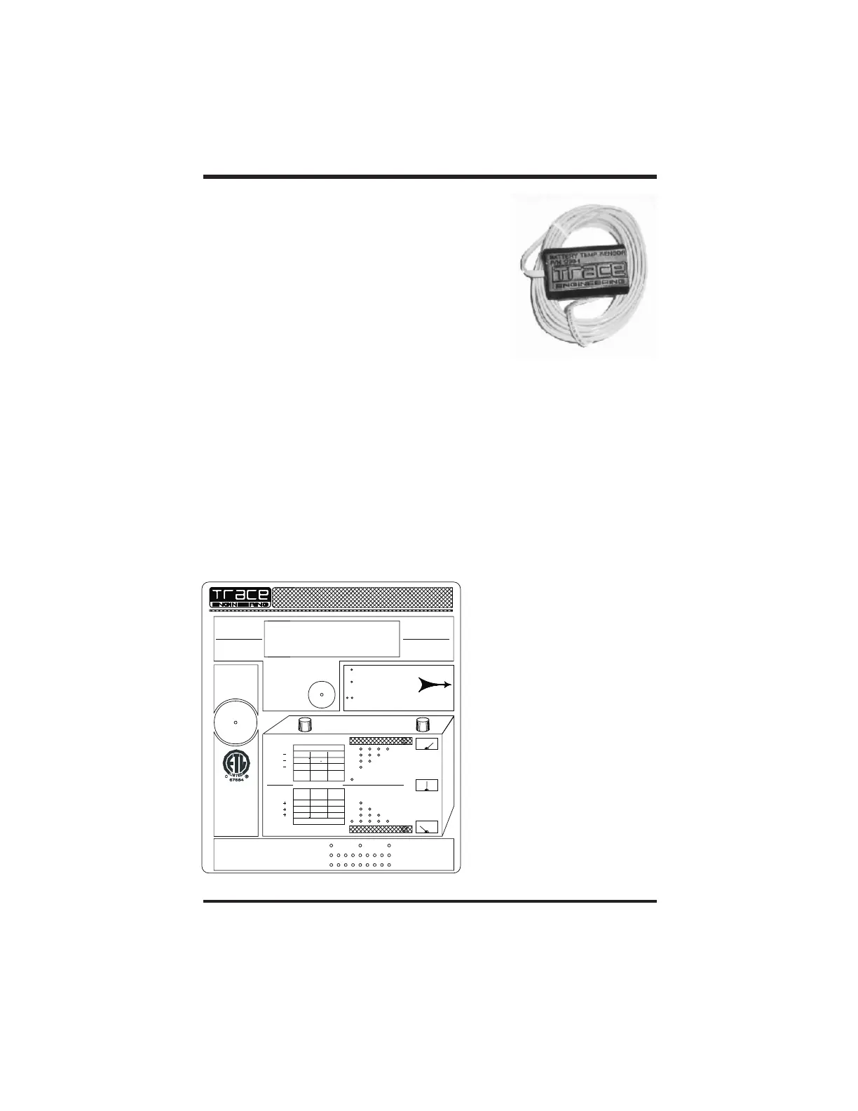
A multi-color LED indicator is provided to indicate the
operating status of the C40. A color-coded label is included
on the cover of the C40 to explain the status LED’s
operation. When the C40 is in Charge Control or Load
Diversion mode, the LED will be green. When in Load
Control mode, the LED will be red. An orange LED indicates an error condition. When
battery equalization is in process, the LED will alternate between red and green.
- The battery has entered the FLOAT stage of the charging process. The
status LED will remain solid unless the batteries drop below the Float voltage setting for an
accumulative period of one hour. This allows the user to confirm that the system reached
FLOAT during the charging process when checked at the end of the day. Reaching the
FLOAT stage frequently is a good indication of proper system operation and will maximize
battery life and performance.
- indicates that the controller is in the Charge Control or Diversion Control
mode and the battery is not fully charged. As the battery voltage approaches the Bulk
setting, the status LED will blink green several times (up to 5) and then pause. This
indicates that the battery voltage is approaching the Bulk setting and provides an indication
of the battery condition.
LED STATUS Indicator
Charge Control or Diversion Control Mode Indications
Solid Green
Blinking Green
Copyright Trace Engineering Co. Inc. Tel (360) 435-8826 Part Number 2680 Rev. C
5916 195 Street, NE Fax (360) 435-2229 November 4, 1998
Arlington, WA 98223 USA www.traceengineering.com Page
th
Green =Charge Control Mode or
Diversion Control Mode
When flashing, battery voltage =
HVD(bulk) setting minus value
shown.
Single green flash = voltage below
lowest HVD setting. See table.
Red = Load Control Mode
When flashing, battery
voltage = LVD setting plus value
shown on table.
Single Red flash = low voltage
Orange = Slow Flash = Low
Voltage
Fast Flash = Error Condition
Red/Green
Equalization in Process
Alternating =
(DVM/C40)
HVD SETTINGHVD SETTING
BATTERY FULL
RESET AMP-HOURS
LVD SETTINGLVD SETTING
REVERSE POLARITYREVERSE POLARITY
0.15V 0.30V 0.45V0.15V 0.30V 0.45V
BATTERY EMPTY
12.60 / 25.20 / 50.4012.60 / 25.20 / 50.40
0.45V 0.90V 1.35V0.45V 0.90V 1.35V
0.30V 0.60V 0.90V0.30V
0.60V 0.90V
CONNECTION OF THE BATTERY OR PV ARRAYCONNECTION OF THE BATTERY OR PV ARRAY
WILL SOUND AN INTERNAL BUZZER. FAILUREWILL SOUND AN
INTERNAL BUZZER. FAILURE
TO CORRECT THIS CONDITION WILL RESULTTO
CORRECT THIS CONDITION WILL RESULT
No 14-M91 SEP 91No 14-M91 SEP 91
IN DAMAGE TO THE CONTROLLER.IN
DAMAGE TO THE CONTROLLER.
INDUSTRIAL POWER
COMMERCIAL AND
SUPPLIES
POWER CONDITIONINGPOWER
CONDITIONING
POWER SYSTEMSPOWER
SYSTEMS
PHOTOVOLTAIC
RESIDENTIAL
UNITS FOR USE INUNITS
FOR USE IN
UL DRAFT 1741
CSA-C22.2
LVD
LVD
LVD
12.0V
HVD
HVD
HVD
0.50V
0.75V
12.0V
0.25V
STATUS LEDSTATUS LED
INDICATOR
AMP HOUR METERAMP HOUR METER
PN 2247PN 2247
TO RESET THETO RESET THE
PUSH AND HOLDPUSH AND
HOLD
FOR 10 SECONDSFOR
10 SECONDS
LOW VOLTAGELOW VOLTAGE
DISCONNECT
EQUALIZE ACTIVATED
OVER CURRENTOVER
CURRENT
OVER TEMPERATURE
OR
E F
START / STOP EQUALIZATION MODESTART / STOP EQUALIZATION MODE
HOLD RESET IN FOR 10 SECONDS TO INITIATEHOLD RESET IN FOR 10 SECONDS TO INITIATE
EQUALIZATION CYCLE. PUSH ONCE TO ABORTEQUALIZATION
CYCLE. PUSH ONCE TO ABORT
48.0V24.0V
1.00V
48.0V
2.00V
3.00V
1.00V
1.50V
24.0V
0.50V
FE
FE
CURRENT
AMP-HOURS
RESETTABLE
ARRAY/LOAD
TOTALIZING
AMP-HOURS
VOLTAGE
BATTERY
WARNING !!!WARNING !!!
(UP TO 1 MINUTE DELAY WHEN(UP TO 1 MINUTE DELAY WHEN
PUSHED - 10 MIN AUTO RESET)PUSHED
- 10 MIN AUTO RESET)
10 MINUTES OF LOAD OPERATION AFTER LVD.10
MINUTES OF LOAD OPERATION AFTER LVD.
ONE PUSH WILL GIVEONE
PUSH WILL GIVE
RECONNECT LOAD
RESET OVERLOAD
SOLID REDSOLID RED
SOLID GREENSOLID GREEN
C40
40 Amp 3 Stage Solar Charge Controller40 Amp 3 Stage Solar Charge Controller
40 Amp DC Load Controller40 Amp
DC Load Controller
OR
7