Installing the DVM/C40
Mounting the C40R
Three Stage Battery Charging
To install the faceplate LCD, first remove the factory-installed faceplate by removing the
four Phillips-head screws, and then pull out the LED indicator near the bottom left corner of
the C40 printed circuit board (PCB). Plug the yellow cable on the DVM/C40 display into the
six-conductor modular RJ15 connector adjacent to the LED that you just removed. Align
the face plate and reinstall the screws. If the LED later needs to be replaced, note that it
will operate in either orientation, except that if replaced incorrectly the color of the status
LED will be reversed. The connecting cable for the display is a six-conductor telephone
cable with modular type connectors (RJ15). Although any telephone-type cable will work,
the cables provided with the displays use stranded and tin plated wire for better
performance and longer life.
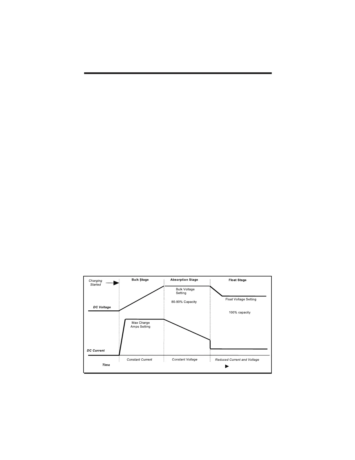
Battery voltage and current vary during the three-stage charging process as follows:
BULK - During this stage the batteries are charged at the Bulk voltage setting and
maximum current utput of the DC source up to 40 amps. When battery voltage reaches the
BULK voltage setting, the controller goes to the next stage. During the bulk charging
process the status LED may blink from one to five times before pausing. The more times it
blinks consecutively, the closer the battery voltage is to the BULK voltage setting.
ABSORPTION - During this stage the voltage of the battery is held at the BULK voltage
setting until an internal timer has accumulated one hour. Current gradually declines as the
battery capacity is reached. During the ABSORPTION stage, the status LED blinks five
times, then pauses and repeats.
FLOAT - During this stage the voltage of the battery is held at the FLOAT voltage setting.
Full current can be provided to the loads connected to the battery during the float stage
from the PV array. When the C40 has reached the FLOAT stage, the status LED will be
solid green.
The C40R is the remotely-mounted digital LCD voltmeter that mounts in a standard double
gang outlet box, which can be permanently installed in a wall or cabinet. The unit can also
be surface mounted with relief behind it, and it can be located up to 1000 feet from the C40
itself. If the DVM meters appear inaccurate or unusual on runs over 100 feet from the C40,
remove the jumper located below the voltage configuration pins on the back of the C40R.
This dims the LCD backlight, reduces power consumption and improves meter accuracy.
16
Copyright Trace Engineering Co. Inc. Tel (360) 435-8826 Part Number 2680 Rev. C
5916 195 Street, NE Fax (360) 435-2229 November 4, 1998
Arlington, WA 98223 USA www.traceengineering.com Page
th