12
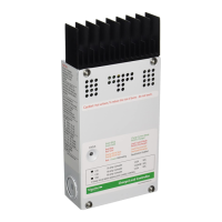
Adjusting the C40
The charge voltage and 0reconnect/disconnect voltage setting of the C40
are adjustable via two rotary potentiometer controls. The knobs are
removable to reduce the likeliness of tampering with the settings.
Calibrated scales are provided to allow setting of the control without
requiring the use of a digital voltmeter. Visual adjustment allows an
accuracy of +/- 0.1 volts.
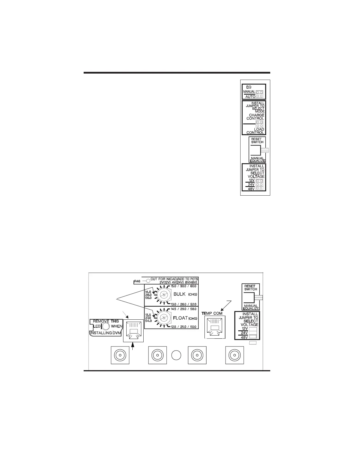
In Charge Control mode or Diversion Control mode, you can adjust the
Bulk and Float charging voltage by adjusting the potentiometers (pots)
located in the bottom center of the C40 circuit board (for more
information regarding Bulk and Float settings, see the Three Stage Battery
Charging Process section of this manual).
The pot scale for Bulk charge voltage is calibrated from 13.0 to 15.0 volts
(when the voltage jumper is set for a 12-volt system) in increments of 0.2
volts, from 26.0 to 30.0 volts (24-volt system) in increments of 0.4 volts, or
from 52.0 to 60.0 volts (48-volt system) in increments of 0.8 volts. For
Float charge voltage, the pot scale is calibrated from 12.5 to 14.5 volts (12-
volt system), 25.0 to 29.0 volts (24-volt system), and from 50.0 to 58.0
volts (48-volt system) with the same increments as above.
At midrange on these scales, a test point is provided for use with a volt meter for assuring
more accurate adjustment. The pots are equipped with removable knobs, to prevent
accidental adjustments by the curious or uninformed. If the knobs are missing, a 5/64” hex-
head driver can be used to adjust the settings. A digital volt meter can be connected from
the BAT NEG terminal on the circuit board and the small testpoint located to the left of each
adjustment pot at the 9 o’clock position. The testpoint provides a reading from zero to two
volts - this value must be added to the lower value of the adjustment range (Bulk=13.0,
Float=12.5, LVR=12.0, LVD=10.5). Multiply this value by 2 for 24 V and by 4 for 48 V.
For example, to set the BULK (HVD) voltage to 14.4 volts, adjust the pot until the testpoint
reads 1.4 volts (13.0 V + 1.4 V = 14.4 V) or to set to 28.2, adjust the pot until the testpoint
reads 1.10 volts [1.10x2(24V)=22+26.0 = 28.2].
Remember to add two volts to the settings when using NiCad type batteries.
Setting Voltage Parameters
Testpoints for Voltage Settings
Copyright Trace Engineering Co. Inc. Tel (360) 435-8826 Part Number 2680 Rev. C
5916 195 Street, NE Fax (360) 435-2229 November 4, 1998
Arlington, WA 98223 USA www.traceengineering.com Page
th
BAT NEG
Press reset for 10 seconds
to initiate reset cycle; press
and release to abort
Potentiometer
Test Points
DVM or Remote
Connection
BTS Connection
BATTERY POSITIVE+
PV NEGPV
NEG
GROUND
METER
Torque: 25 IN LBTorque:
25
IN LB
PV POS/LOADPV POS/LOAD
/LVR