7
EN
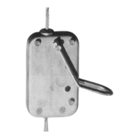
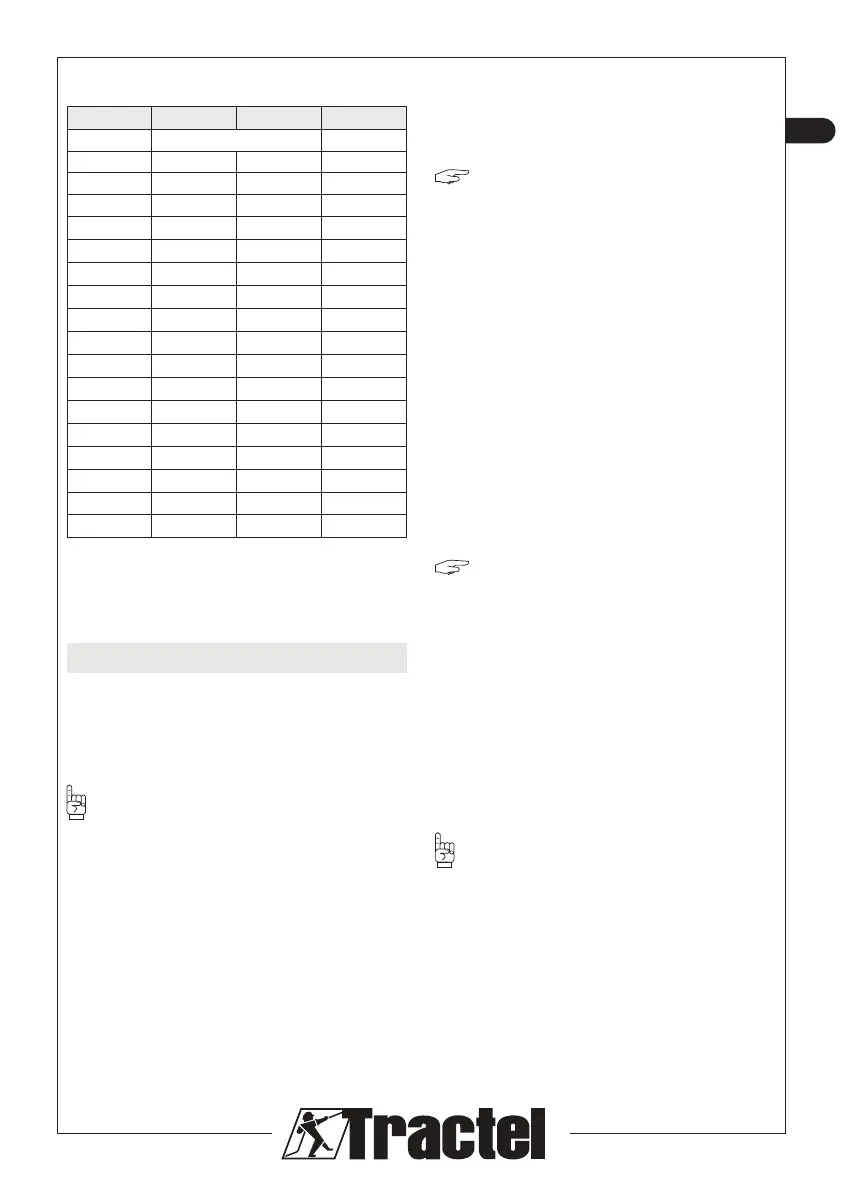
• The dimensions (in mm) of the Blocstop™ BS
fall arrest devices are as follows:
Series BS 15 BS 20 BS 35
Fig. n° 24 n° 25
a. 161 203 290
b. 167 210 297,5
c. 209 252 375,5
d. 91 121 140
Øe. 12 12 22
o. 74 74 115
g. 64 74 90
h. 38 38 60,5
i. 20 19,5 22
j. 14 25 28
k. 42,5 55 60
l. 39 50 12,7
l*. 100 145 157
m. 33 45,5 90
m.* 39 52,5 84
r. 19 19 27,5
Øs 12,2 12,2 22,2
Table 4
(*): Position of stirrup used to unlock fall arrest
device.
5. Installation
As specied in §2, the BS fall arrest device
can be used on material’s lifting and pulling
installations.
5.1. Installation of fall arrest devices
IMPORTANT: The fall arrest device
mounting system must provide a tensile strength
of at least four times the nominal capacity of
the Blocstop™ BS fall arrest device. This is
indispensable to ensure the mechanical strength
of the installation should a fall occur.
Before you begin to install the fall arrest device,
check that the unit is in good visible condition
and, in particular that:
– there are no signs of impact or deformation on
the fall arrest device,
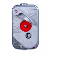
– the stirrup (item d, g. 1) swivels freely on its
swivel pin,
– the marking on the device is legible and
compliant with the information in the “markings”
section for the unit,
– the holes (items a and f, g. 1) are neither
soiled or obstructed.
“NOTE”: The fall arrest device is supplied
with a shackle (item e, g. 1) optionally. Any other
shackle having the following characteristics can
be used:
– BS 15 and BS20: shackle (min. opening A = 38
mm, g. 26, with Ø12 pin and cotter pin (item h,
g. 1) with working load limit of 1.6 t.
– BS35: shackle (min. opening A = 55 mm,
g. 33, equipped with Ø22 pin and a cotter pin
(item h, g. 1) with working load limit of 3.2 t.
5.2. Preparation of wire ropes
See §5.4.
5.3. Assembly and installation of lifting
wire rope in fall arrest device for a
load lifting or pulling installation
(g. 21)
”NOTE”: The fall arrest device can
be adapted to any lifting or pulling device
implementing a feed-through wire rope
(TIRFOR
®
manual hoist or TIRAK™ electric
hoist) equipped with a TIRFOR
®
or TIRAK™
wire rope.
Fig. 21 illustrates installation of the fall arrest
device with a TIRFOR
®
hoist implementing
a feed-through wire rope; the installation
procedure is as follows:
– secure the fall arrest device (item 3, g. 21) by
its shackle (item 6, g. 21) to the anchor point
(item 8, g. 21) using a sling (item 1, g. 21).
IMPORTANT: make sure that the fall arrest
device is always properly aligned with the lifting
or pulling wire rope and that the slack in the sling
does not exceed 5 cm to prevent any excessive
jolting if a lifting or pulling system failure occurs.
– secure the TIRFOR
®
(item 2, g. 21) to an
anchor point (item 10, g. 21),
– release the TIRFOR
®
to allow insertion of the
wire rope (see TIRFOR
®
manual),