T10 Installation Notes v1.7
Generic T10 Installation Notes v1.7.doc 12.08.2015
Page 14
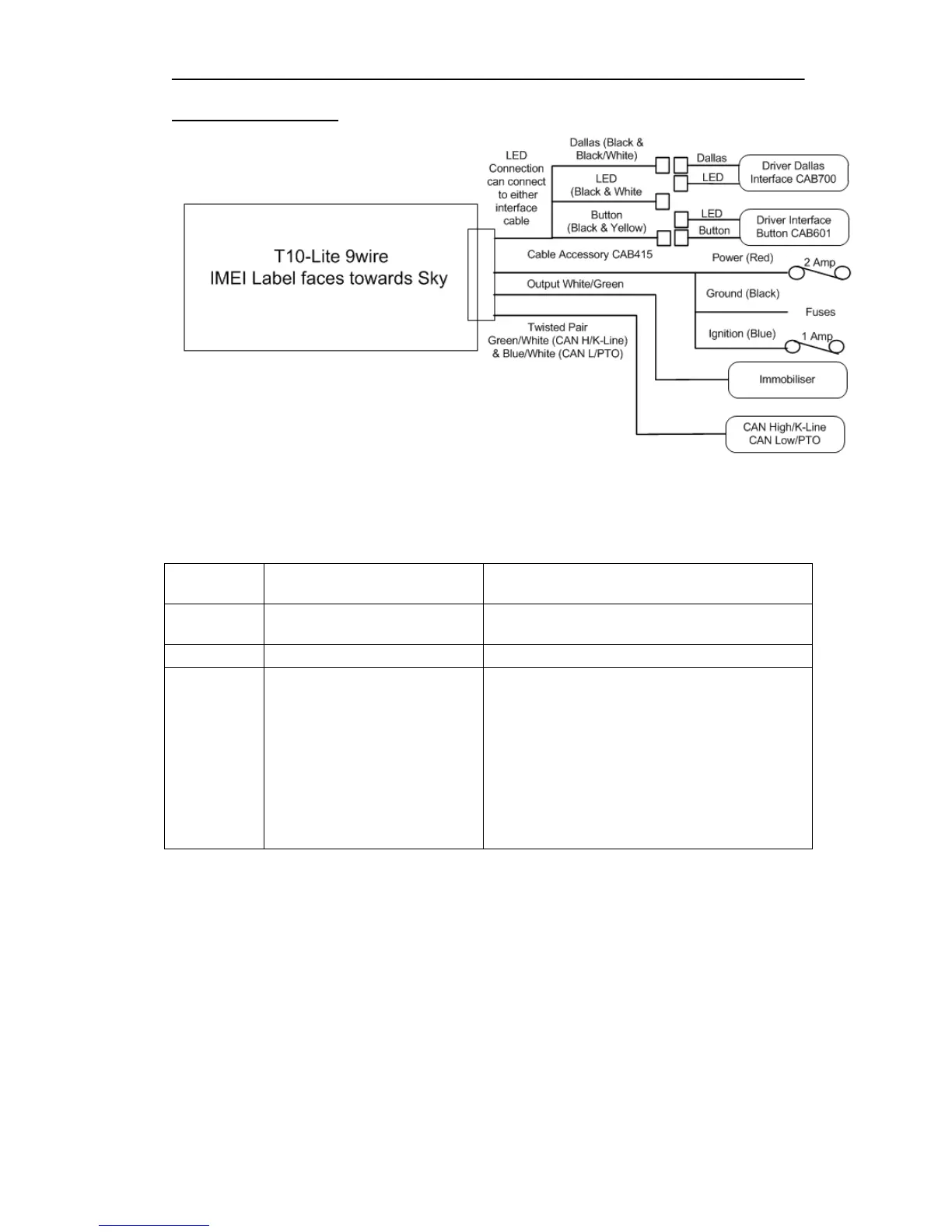
T10-Lite 9wire System
There are 4 main cable options used with the T10-Lite (CAB400, CAB405, CAB410 and CAB415).
These all have the same wire colour coding and location for the Power, ground and Ignition and
are connected as follows:
Vehicle Supply Positive (+ve)
Connect to a permanent Positive supply (6 to
30V) via a 2 amp in-line fuse.
Vehicle Supply Negative (-ve)
Connect to permanent Negative supply.
Ignition Sense Positive (+ve)
switched (active high)
Connect to a switched ignition line via a 1 amp
in-line fuse. This ignition line should be a true
engine running signal to ensure that journey’s
are detected correctly. If true engine run is not
accessible, a second stage engine signal is
acceptable as long as ‘Smart Ignition’ is being
used in the configuration. This must be a
primary or “D circuit” connection. An auxiliary
ignition connection is NOT acceptable as this
will result in incorrect operation of the product.
It is highly desirable that these connections are soldered to ensure a good permanent connection
to the vehicle supply and ignition points. It is not the intention of this manual to cover all
electrical connection points for all vehicle types and therefore the experience of qualified fitting
staff is essential to ensure that suitable location points are found for the vehicle in question.
It is strongly recommended that power pick up points are chosen that DO NOT form part of an
auxiliary supply such as cigar lighter or auxiliary power sockets as these can be compromised by
the connectivity of third party devices such as power chargers, invertors, heating elements, tools
etc.