18-GJ96D1-1B-EN
53
Replacement AHC configuration – 24 volt mode
Replacement AHC boards need programmed and will not run without
configuration IN 24 Volt Mode. There are 2 ways to perform the
configuration. 1 of the methods is required to get the unit running.
Combining 2 or more methods will result in unwanted operation.
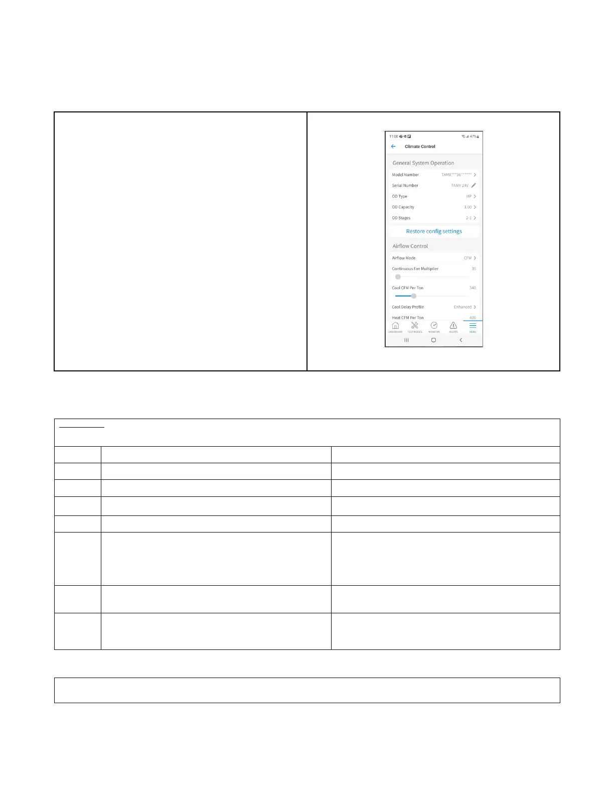
1. The most complete configuration will be accomplished using the
Diagnostics Mobile App. In this app, there are configurations for
the model number, blower delays and accessories.
2. There is a Button Press method is to configure the size of the Air
Handler and is accomplished by pressing the S1 button on the
bottom of the control board in a sequence explained in this
document.
Only 1 of these methods should be used.
Method #1:
Button Press AHC Configuration Method: Method #2
Table 29. Configuration for Replacement AHC
Replacement AHC will need to be configured for unit size. Airflow will be set at 400 cfm/ton based on unit size configuration. These
configurations can be done through the Diagnostics Mobile App with no manual steps or can be done manually without the Diagnostics Mobile
App.
Step Manual Program Unit Model Size Red LED Status
1
Hold BLE button for 5 seconds and release. Red LED will be off.
2
1 Red flash that indicates system is ready to program. 1 Red LED flash alerts user that it is now able to program.
3
If configuration is present, Red LED will flash based on the
configuration.
Red LED will be off if no configuration is present.
4
5 quick Red LED flashes. 5 quick Red LED flashes.
5 Start programming by clicking BLE button. 13 press - 5TAMXB02AV21DAA
14 press - 5TAMXC03AV31DAA
15 press - 5TAMXD04AV31DAA
16 press - 5TAMXD05AV41DAA
17 press - 5TAMXD06AV41DAA
18 press - 5TAMXD07AV51DAA
6 After the last button press, Red LED will flash 1 time to
acknowledge programming.
Red LED will now flash the number of times you pressed to
confirm your configuration. If you programmed the wrong size,
within 2 seconds, start step 5 over.
7
Red LED will announce successful programming. Red LED will turn on for 5 seconds announcing the
configuration has been stored in NV memory correctly. Red LED
will be on for only 2 seconds if not stored properly.
Programming is complete.
Replacement AHC configuration — LINK Communicating Mode:
The system controller (SC360) will load important parameters in communicating mode and no interaction is necessary when replacing the AHC.
IF the AHC and the System Controller (SC360) need replaced at the same time- contact your local FSR or technical support agent.