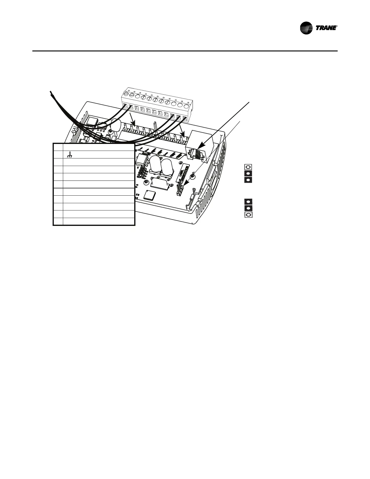
Figure 1. Attaching the terminal block to the pins on the circuit board
11 24 VAC/VDC
10 (GROUND)
9
8
7COMM–
6COMM+
5 HEAT SETPOINT (HSP)
4 SYS/FAN MODE (MODE)
3 SETPOINT
2 SIGNAL COMMON (COMMON)
1 ZONE TEMPERATURE (ZONE TEMP)
S2 REMOTE TEMP SENSOR
S1 REMOTE TEMP SENSOR
]
RJ11 (RJ22 compatible)
connection for a Trane service tool
If jumper is positioned as
shown here, the display
shows the local temperature
sensor reading (default).
If jumper is positioned as
shown here, the display
shows the external
temperature sensor reading.
Jumper is installed from factory to
display local temperature reading. To
enable external sensor option, move
jumper to “Ext” location.
Local
Ext
BAS-SVX10F-EN 13
Installation and Configuration: Display Sensor
6. Push the excess wire into the wall cavity and plug it with nonflammable insulation to prevent
drafts from affecting the sensor.
Important: Do not coil excess wire inside the back plate.
Configuring the Display Sensor
The configuration of the display sensor determines which system features can be accessed and
changes can be made by the tenant (for example, changes to cooling/heating mode, setpoint, or
fan speed. Verify system and associated unit features before configuring the sensor.
The building owner or operator may choose to limit tenant access to certain features. This can be
done through configuration. Or, if a sensor is configured to match all controllable features of the
associated equipment, the locking feature can be used to restrict the tenant from making changes.
Configuration Procedure
To configure settings on the sensor, follow this procedure in the order presented.