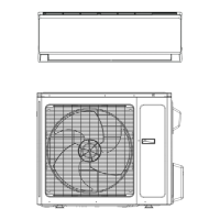
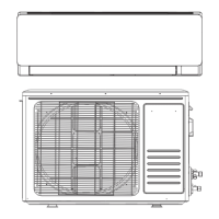
17 Series Mini-Split
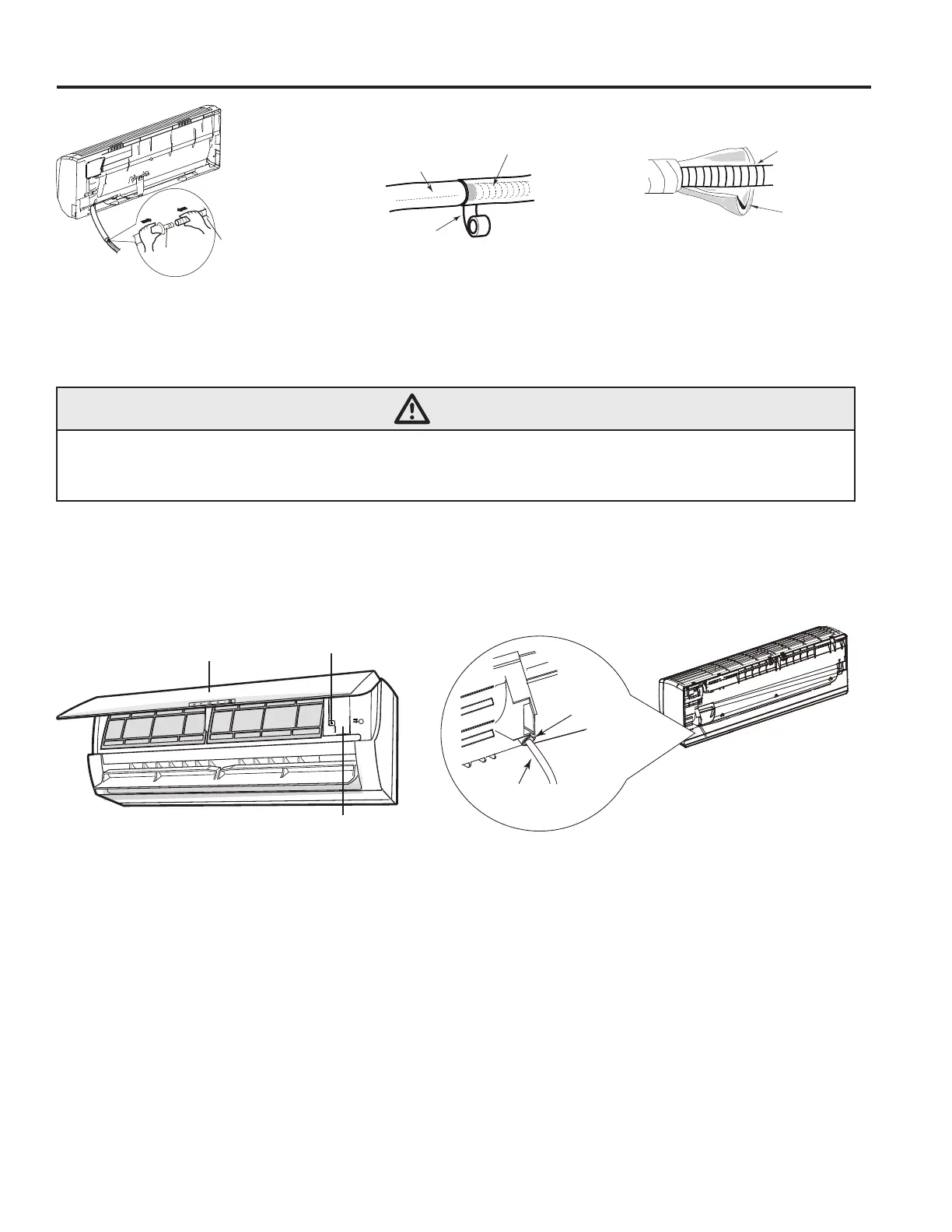
Outlet
pipe
Drain hose
Drain hose
Tape
Outlet pipe
Drain hose
Insulating pipe
Fig. A
Fig. B
Fig. C
Wiring at the Indoor Unit
WARNING
Disconnect all electrical power and discharge all energy storing devices such as capacitors to
the outdoor unit(s) prior to wiring the indoor unit(s) to avoid risk of death, injury, or damage to
equipment.
1. Open the front panel of the indoor unit, remove the screw on the wiring cover and remove the
cover (shown in Fig. D below).
2. Thread the power connection wire through the cable-cross hole at the back of the indoor unit
and pull it through to the front side (shown in Fig. E below).
wiring cover
screw
panel
power connection
wire
cable-cross
hole
Fig. D
Fig. E
3. Remove the wire clip and connect the power connection wire to the wiring terminal according
to the correct color coding. It is recommended to use 4 wire colors (for example: Blue, Black,
Red, Green. Connect Blue to 1, Black to 2, Red to 3 and Green to Ground). All wiring shall
use ring or spade type crimped or soldered connectors (as shown in the outdoor unit installation
section or manual). Ensure electrical connections are tight and strain reliefs are in place.
Regardless of wire color used, The wire terminals labeled 1, 2, 3 and ground must be landed on
the corresponding terminal in the outdoor unit.
4. Put the wiring cover back on the unit and tighten the fastener.
5. Close the front panel.
6. The primary disconnect for both the indoor and outdoor unit shall be wired to disconnect the
branch circuit feeding the outdoor unit. The Indoor unit obtains high voltage and communication
from the outdoor unit. If the AHJ (authority having jurisdiction) requires a branch circuit
 Loading...