7 GAM5-SF-1P-EN
Note: Heating and cooling speeds are the same, factory
set at Speed Tap #4.
Note: A “G” only signal from the comfort control will run
the blower at a lower speed, factory set at Speed Tap #1.
See the Sequence of Operation for additional information.
Note: Speed Tap 1 is NOT used for two stage systems.
Two stage systems will require an airflow adjustment.
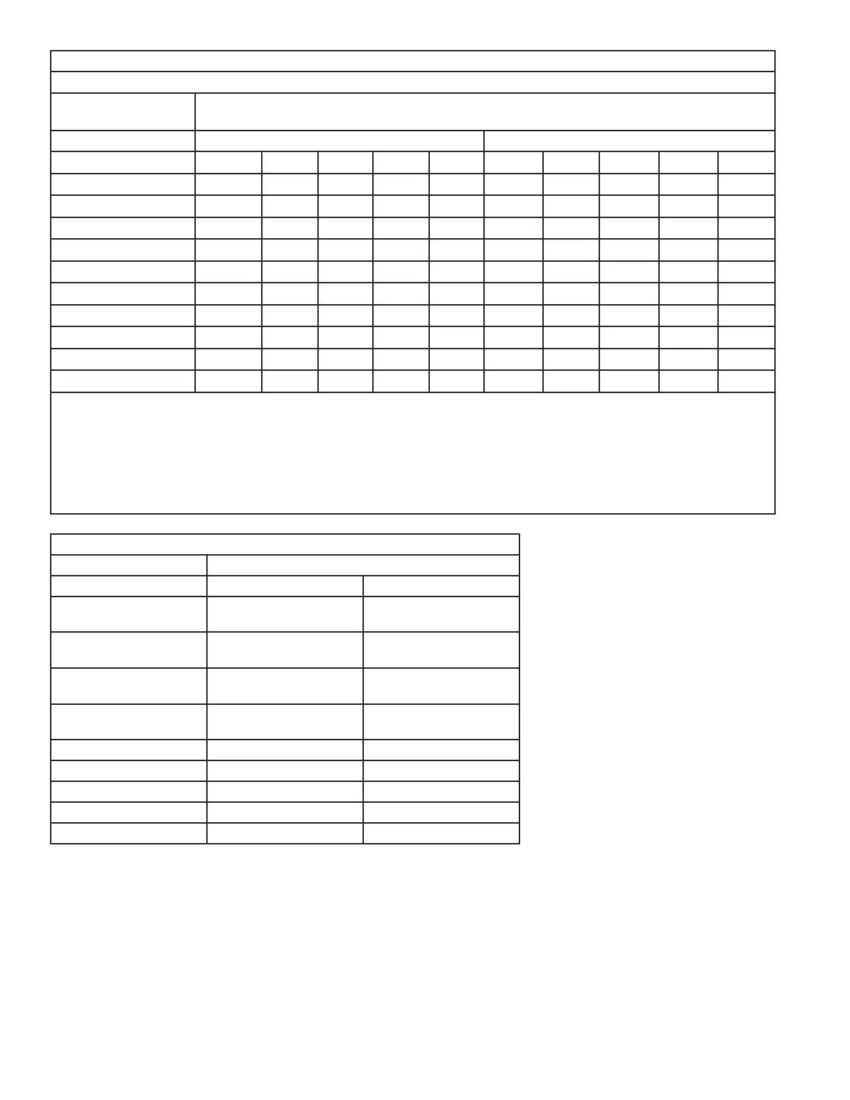
AIRFLOW PERFORMANCE
GAM5B0C42M31SB, GAM5B0C42M31EA
EXTERNAL STATIC
(in w.g)
AIRFLOW (CFM)
Speed Taps - 230 VOLTS Speed Taps - 208 VOLTS
5 4 † 3 2 1 5 4 † 3 2 1
0 1644 1575 1401 1266 752 1641 1572 1398 1263 749
0.1 1596 1525 1346 1215 665 1590 1519 1340 1209 659
0.2 1550 1480 1300 1157 569 1542 1471 1291 1148 560
0.3 1509 1437 1252 1110 492 1497 1425 1241 1099 480
0.4 1463 1391 1205 1058 384 1449 1377 1191 1043 370
0.5 1420 1345 1151 980 327 1403 1328 1134 963 310
0.6 1376 1301 1085 917 259 1356 1282 1066 898 239
0.7 1332 1251 1020 865 - 1310 1228 998 842 -
0.8 1271 1179 969 813 - 1246 1154 944 788 -
0.9 1199 1119 924 747 - 1171 1091 897 719 -
NOTES:
1. Values are with wet coil and without filters.
2. Contact your particular filter manufacturer for pressure drop data.
3. Electric heater pressure drop is negligible and is included within the airflow data.
4. Tap 1 is an continuous fan speed tap for single stage systems. Airflow adjustment is required for 2 stage systems.
See Airflow adjustment section.
5. † Factory Setting
GAM5B0C42M31SB, GAM5B0C42M31EA MINIMUM HEATER AIRFLOW CFM
Heater Minimum Air Speed Tap
Without HP With HP
BAYEAAC04BK1
BAYEAAC04LG1
Tap 2 Tap 3
BAYEAAC05BK1
BAYEAAC05LG1
Tap 2 Tap 3
BAYEAAC08BK1
BAYEAAC08LG1
Tap 2 Tap 3
BAYEAAC10BK1
BAYEAAC10LG1
Tap 2 Tap 3
BAYEAAC10LG3 Tap 2 Tap 3
BAYEABC15BK1 Tap 3 Tap 4
BAYEABC15LG3 Tap 3 Tap 4
BAYEABC20BK1 - -
BAYEACC25BK1 - -
 Loading...


