10
WARNING
The mounting screws must be positioned no
more than 1" from the coil base and more than
4.72" from either side of the coil.
WARNING
Only qualified installers/technicians should attach coil to furnace/ductwork, failure to follow instructions properly could
result in a screw damaging either the coil or drain-pan and could void the warranty.
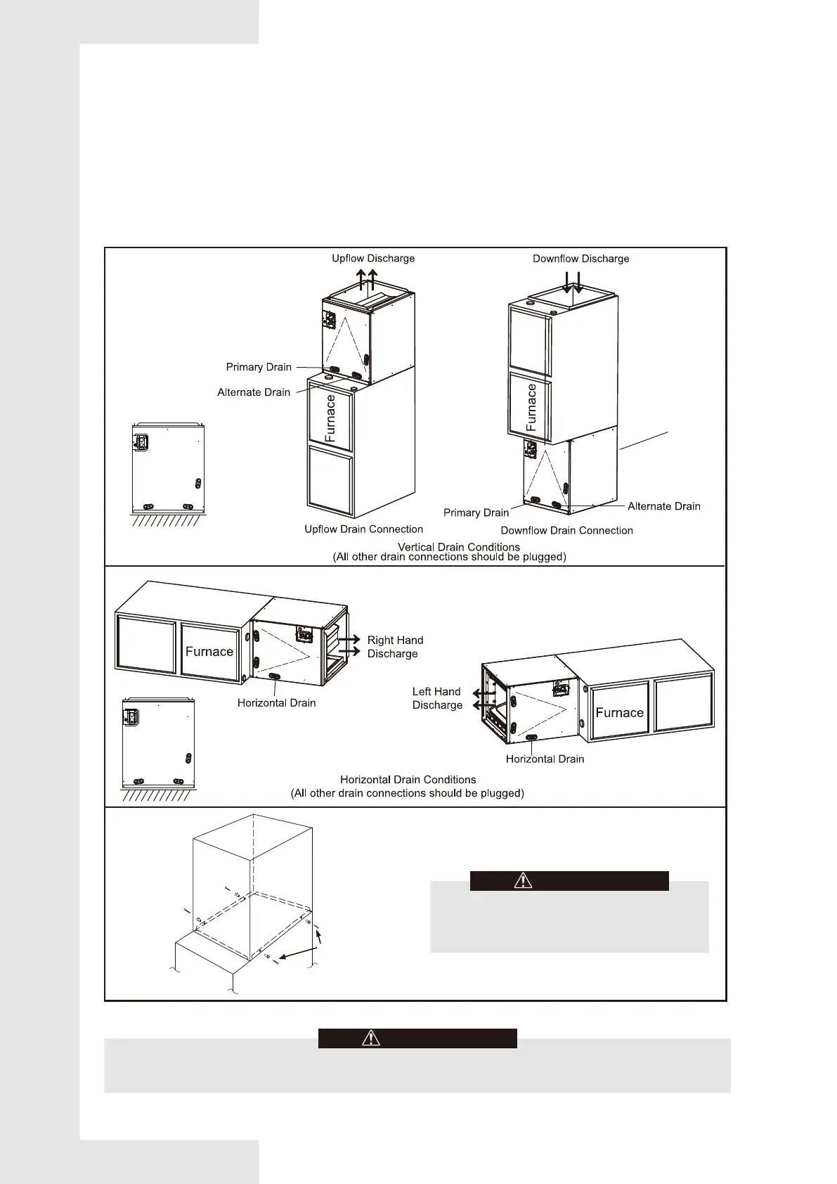
3.3 Installation and Trap Connection
Fig. 3-1 INSTALLATION OF CASED COIL
1. See Fig. 3-1 for coil installation and drain connection.
2. Installation notes:
A. Shut off or disconnect gas furnace's power and remove gas pipe if necessary.
B. Disconnect and remove a sufficient portion of the supply ductwork to provide clearance for the cased coil.
C. Ensure that the coil is leveled well and seal the gap between coil and furnace. See Fig. 3-1. In case that coil and furnace
sizes are not matched, use proper size of sheet metal or other material to fill the gap and seal the gap to prevent air leak.
D. Reconnect the ductwork to the coil case, and seal any leakage.
E. Reconnect Power line on gas furnace, turn on the furnace to check any sign of leakage.
F. The installation method shall refer to the requirements of gas furnaces and on site installation conditions.
Steps:
1.place the coil case on the top/bottom of
furnace as shown.
2.align coil case with the furnace outlet,use
self-tapping screws to connect coil case and
furnace as shown in Fig.3-1.
3. seal for air leaks as required.
The coil is installed
under the furnaces
FURNACE
CASED
COIL
SCREWS
(BOTH SIDES)
Steps:1.attach the coil case on the top/bottom of
furnace as shown.
2.align coil case with the furnace outlet,use
self-tapping screws to connect coil case and
furnace as shown in Fig.3-1.
3. seal for air leaks as required.