22
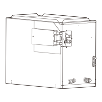
5 REFRIGERANT LINE
The suction pipe and liquid pipe of the indoor unit need to
be protected and cannot be grabbed when moving the
indoor unit.
Keep the coil connections sealed until refrigerant
connections are made. See the Installation Instructions
for the outdoor unit for details on line sizing, tubing
installation, and charging information.
Coil is shipped with Nitrogen. Evacuate the system
before charging with refrigerant.
Install refrigerant tubing so that it does not block service
access to the front of the unit.
Nitrogen should flow through the refrigerant lines while
brazing.
Use a brazing shield to protect the cabinet’s paint and a
wet rag to protect the rubber grommet and TXV seal ring
from being damaged by torch flames.
After the refrigerant connections are made, seal the gap
around the connections with pressure sensitive gasket.
The pipework, including the piping material, pipe routing,
and installation, must be protected from physical damage
during operation and service. It should also comply with
national and local codes and standards, such as
ASHRAE 15, ASHRAE 15.2, IAPMO Uniform Mechanical
Code, ICC International Mechanical Code and CSA
B52.prior to being covered or enclosed, the pipework
should undergo inspection to ensure compliance. All filed
joints shall be accessible for inspection prior to being
covered or enclosed.
All joints made in the installation between parts of the
refrigerating system, with at least one part charged, shall
be made in accordance with the following:
— A brazed, welded, or mechanical connection shall be
made before opening the valves to permit refrigerant to
flow between the refrigerating system parts. A vacuum
valve shall be provided to evacuate the interconnecting
pipe or any uncharged refrigerating system part.
— Mechanical connectors used indoors shall comply with
ISO 14903. When mechanical connectors are reused
indoors, sealing parts shall be renewed. When flared
joints are reused indoors, the flare part shall be
refabricated.
— Refrigerant tubing shall be protected or enclosed to
avoid damage.
— Flexible refrigerant connectors (such as connecting
lines between the indoor and outdoor unit) that may be
displaced during normal operation shall be protected
against mechanical damage.
Compliance is checked according to the installation
instructions and a trial installation, if necessary.
Field-made refrigerant joints indoors shall be tightness
tested. The test method shall have a sensitivity of 5
grams per year of refrigerant or better under a pressure
of at least 0.25 times the maximum allowable pressure.
No leak shall be detected.
After completion of field piping for split systems, the field
pipework shall be pressure tested with an inert gas and
then vacuum tested prior to refrigerant charging,
according to the following requirements.
The minimum test pressure for the low side of the system
shall be the low side design pressure and the minimum
test pressure for the high side of the system shall be the
high side design pressure, unless the high side of the
system cannot be isolated from the low side of the
system in which case the entire system shall be pressure
tested to the low side design pressure.
Use a wet rag to protect the two seal ring in the
input pipe from being damaged by torch flames
while brazing.
After the brazing work is finished, make sure to check if
there is refrigerant leakage. After checking for vapor
leaks, be sure to insulate the pipe connections
referring.
CAUTION
It is recommended to install a filter drier, the filter
drier should be installed in the liquid line
between the outdoor unit's liquid line service
valve and the indoor coil's metering device. The
filter drier should be compatible with R454B
refrigerant.
NOTE
— Mechanical joints in compliance with ISO 14903 or UL
207 (U.S. only).
— Welded or brazed joints.
— Joints in enclosures that vent to the unit or to the
outside.
Compliance is checked by inspection and tests.