24
7 AIRFLOW PERFORMANCE
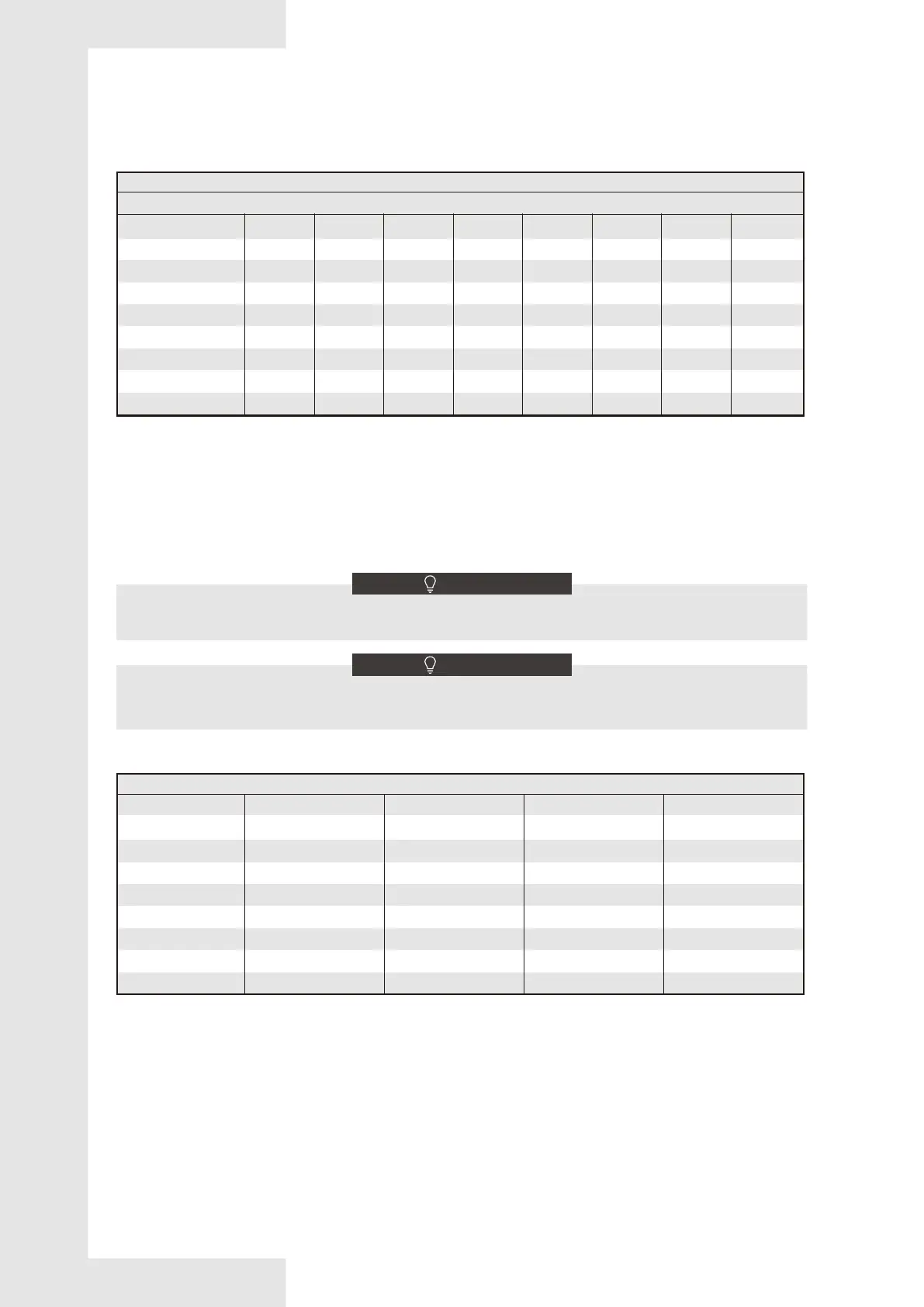
Airflow performance [CFM VS Pressure drop]
Pressure drop characteristics for cooling and heat pump coils
Pressure drop (Inches of water)
Model
Model Upflow
1200
1250
1250
1575
1575
1575
1850
2000
Horizontal Left
1050
1200
1200
1400
1400
1450
1750
1850
Downflow
1050
1050
1050
1400
1400
1450
1750
1850
Horizontal Right
1200
1250
1250
1575
1575
1575
1850
2000
0.05
307
327
496
456
505
533
439
466
0.1
485
527
718
638
726
857
699
764
0.15
618
682
924
810
932
1105
906
978
0.2
729
810
1102
953
1098
1319
1071
1157
0.25
823
925
1259
1077
1244
1509
1224
1313
0.3
911
1024
1398
1191
1375
1675
1362
1466
0.35
991
1122
1530
1284
1494
1824
1487
1590
0.4*
1063
1217
1651
1390
1604
1956
1589
1695
Data based on wet coil with entering air at 80 deg F DB / 67 deg F WB without air filter.
The maximum allowable pressure drop is 0.4 in H
2O.
The maximum CFM is the data at 0.4 in H
2O pressure.
Maximum airflow setting
Water blow-off could occur in certain installation positions if the airflow setting exceeds the maximum values listed.
NOTE
Airflow should not exceed the maximum airflow setting specified in Table 7-2. Exceeding these CFM limits may result
in water blowing from the coil surface and into the ductwork.
NOTE
Table 7-1
Table 7-2
5MXCA003AC6HCA
5MXCB004AC6HCA
5MXCC005AC6HCA
5MXCB006AC6HCA
5MXCC007AC6HCA
5MXCD008AC6HCA
5MXCC009AC6HCA
5MXCD010AC6HCA
5MXCA003AC6HCA
5MXCB004AC6HCA
5MXCC005AC6HCA
5MXCB006AC6HCA
5MXCC007AC6HCA
5MXCD008AC6HCA
5MXCC009AC6HCA
5MXCD010AC6HCA
Maximum airflow setting (CFM)