16
System refngerant charge
(lb) ♦
Minimum Airflow Setting
(CFM)
less than 4
4
5
6
7
8
9
10
11
12
13
14
15
16
17
18
19
20
no mimimum
108
135
162
189
216
244
271
298
325
352
379
406
433
460
487
514
541
Minimum Airflow Setting
♦ The system refrigerant charge is the total system charge
which is marked on the system according to the instructions
provided by the manufacturer of the outdoor unit.
3.6.1.2 Installing the refrigerant leak mitigation
control kit
1. Turn off all power supplies of gas furnace, outdoor unit
and wire controller.
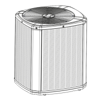
2. Open the upper cover of the leak mitigation control
kit,and fix the kit on the front or side of Acoil with
self-tapping screws. Pay attention to the sponge pad in
the accessory bag. This should be placed on the back of
the mitigation kit to avoid damage to the A-Coil. See
example in fig 3-6.
3. According to the wiring diagram, connect the mitigation
board and the signal cables of the gas furnace, outdoor
unit and wire controller respectively. Note that the
connection cables should use 18AWG specifications.
4. Install the top cover of the mitigation control kit.
5. Power on the gas furnace and outdoor unit
respectively, and check whether the gas furnace and
outdoor unit are running normally.
Installation precautions:
(1) Only install the mitigation kit in the designated
locations to avoid damaging the coil.
(2) When installing the mitigation control kit, do not
use screws more than 0.4 inches long to prevent
screws from penetrating the glass fiber cotton;
(3) When installing the mitigation control kit,
please check that the screws are away from the
coil tubes when installed;
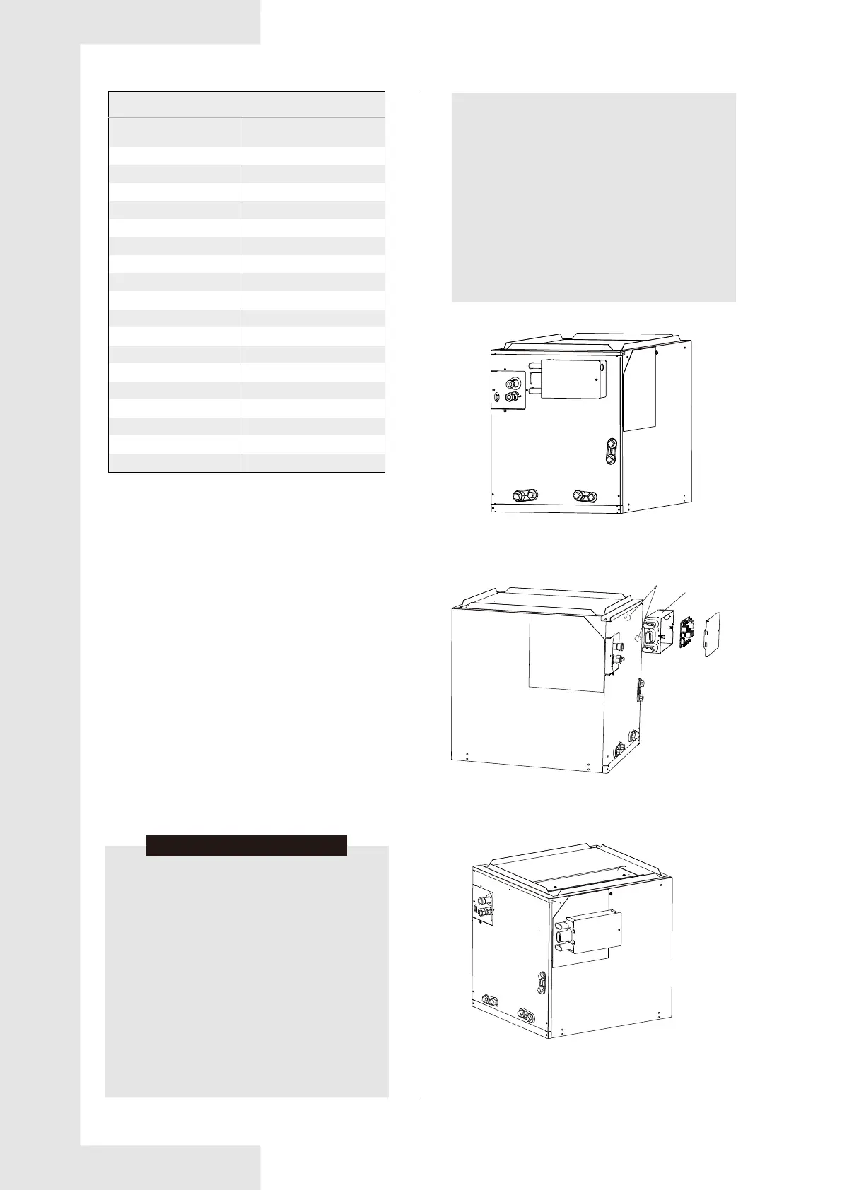
(4) When mounted on the side, the electric control
box can be aligned with the indicating label
arrangement, as shown Fig. 3-7 and Fig. 3-8;
(5) In the side installation, if the drill is used during
installation, the drilling depth should not exceed
0.2 inches to prevent the glass fiber cotton from
being hit;
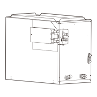
(6) When installing the mitigation kit on the front
panel, use the locating dimples in the panel as
shown in Fig. 3-6;
(7) The kit is not allowed to be installed in the
lower half of the coil front panel because there is a
coil inside that could be punctured by screws. This
area is shown by the shaded area in Fig.3-5.
NOTICE
Fig. 3-5 Front view
Fig. 3-6 Mounting section view
Fig. 3-7 Install right view
Dimples
for install
Sponge in
the back of
the electrical
box