ACC-SVP01B-EN • BCI-I Integration Guide 5
BCI-I Configuration
BCI-I Configuration
This section will provide the following information when configuring the BCI-I:
• Overview
• Starting a session of Tracer TU and direct connection
• Resetting to factory default
• Configuring IP units
• Configuring BACnet objects
• Changing baud rate and device ID
• Input/output and equipment functions
Overview
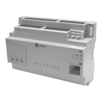
The BCI-I device is designed as a self-configuring controller to accommodate the many possible
equipment configuration options available in the IntelliPak line of equipment. This self-configuring
device eliminates the need for the BAS technician having to create BACnet objects, minimizes the
risk of object configuration errors, and allows the IntelliPak unit to be quickly installed in the BAS.
The self-configuration process only creates objects that are appropriate for the feature set of the
specific IntelliPak unit the BCI-I is connected to. Once this process is complete, the device exits
factory mode and enters the normal mode of operation. At this point, the self-configuration process
will not
start when power is applied to the device.
The set of objects listed in Table 3 , p . 24 through Table 10, p. 31, are the super set of all possible
objects supported by the IntelliPak line of equipment. The BAS technician should query the device
for the list of actual objects that have been created in the device.
Starting a Session of Tracer TU and Direct Connection
Tracer TU is the service tool software that allows the technician to modify the operation of the
device and to discover the BACnet objects present in the device. To modify the device or discover
objects, the user must first connect to Tracer TU as follows:
WARNING: Remove power from the HVAC equipment before opening
electrical control panel.
1. Connect a USB cable directly between the laptop PC and the service port located on the front
of the BCI-I device. When connecting to the controller for the first time, the Found New
Hardware Wizard appears. Follow the wizard instructions to install the USB hardware driver.
2. Click either the Tracer TU desktop icon or the Tracer TU program item in the Tracer TU group
on the Start menu. The Tracer TU splash screen appears briefly followed by the Connect
dialog box.
3. Select the Direct Connection (Via USB cable) radio button if it is not already selected.
4. Click the Connect button and the Tracer TU main page will appear after successful connection.
Note: The BCI-I may be powered via the USB cable or 24 Vac from the HVAC unit. Concurrent
connection of unit power and the USB cable will not harm the BCI-I device.
For more detailed information about direct connection to Tracer TU, refer to the Tracer™ TU Service
Tool Getting Started Guide (TTU-SVN02) (X39641083).