ACC-SVP01B-EN • BCI-I Integration Guide 13
BCI IntelliPak Rotary Switches and LEDs
LEDs Description, Behavior, and Troubleshooting
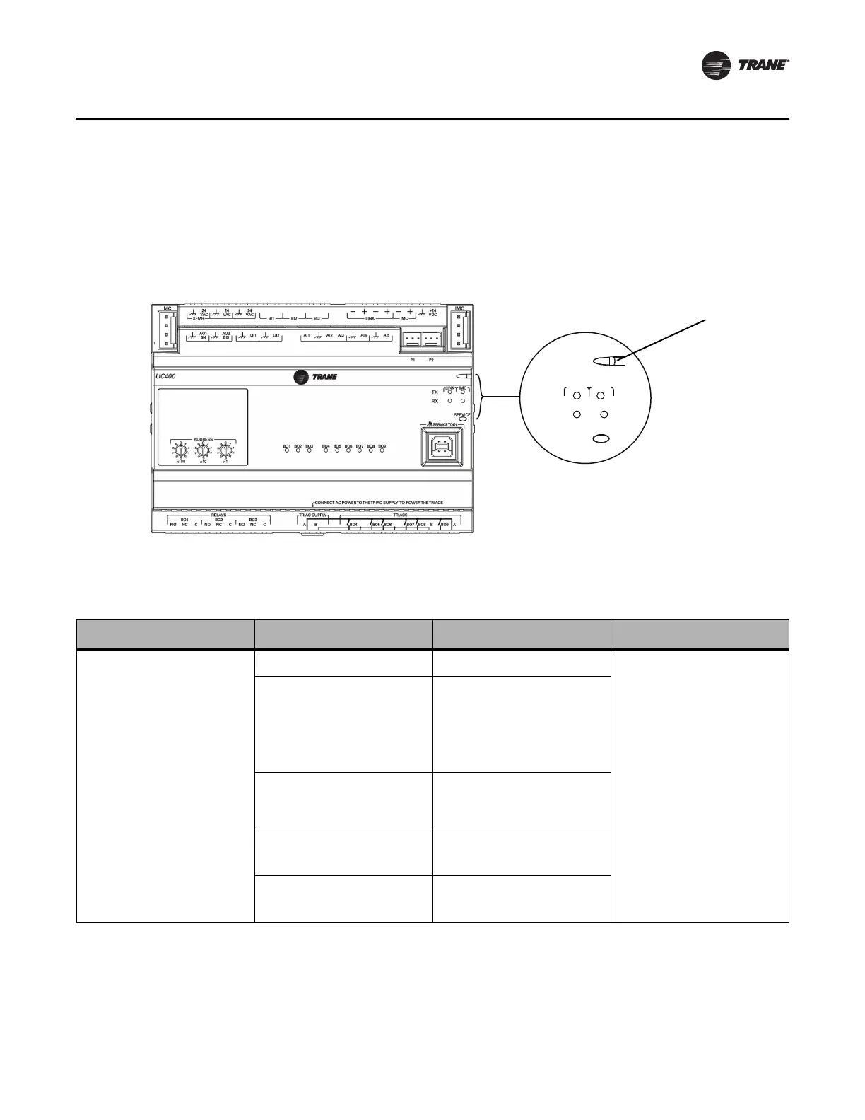
There are 15 LEDs on the front of the BCI-I unit. However, LEDs BO1 through BO9 are not used for
the BCI-I controller. Figure 2 shows the locations of each LED. The following table provides a
description of each LED activity, an indication or troubleshooting tips for each, and any notes.
Figure 2. LED locations
SERVI
C
E
IM
C
LINK
RX
TX
Table 1. LED Activities and Troubleshooting Tips
LED Name Activities
Indication or Troubleshooting
Tip (Denoted in Bullets)
Notes
Marquee LED
Shows solid green when the unit is
powered and no problems exist
Indicates normal operation
Shows solid red when the unit is
powered, but represents low power or a
malfunction
• If low power; could be under voltage
or the microprocessor has
malfunction. Follow the troubleshoot
procedure “24 Vac Measurement,”
p. 15 to measure for the expected
value range.
• If malfunction; unpower and then
repower unit to bring the device back
up to normal operation.
Shows blinking red when an a BACnet
object is in a fault condition
Alarm; when an alarm is triggered, for
example, when a point goes into fault
condition because of point failure or
there is an indication of a custom alarm
in TGP2
Shows blinking green when the device
does not detect the IMC buss
• Verify that the IPC wiring harness is
connected to the IMC link terminals.
• Verify the polarity of the IPC wiring
harness at the unit terminals.
LED not lit
Indicates power is OFF or there is a
malfunction
• OFF or malfunction; cycle the power.
 Loading...