Installation
22 PART-SVN228B-EN
CGAM100, CGAM110, and
CGAM120 Chillers (W2 Units)
Table 26. Kit contents FMF14464
# Qty Per Component Part Component Description
1 8 571272480100 PANEL; LVRD UPPER PLASTIC
2 24 X32030872010 CLIP-SPEED; S Type Spring
3 40 X25020604010 SCREW;M8 X 1.25MM X 16MM
4 2 572024130100 ANGLE; LOUVER
5 8 572055580100 LOUVER; LOWER SIDE CGAM
6 1 572018650100 ANGLE; LOUVER
7 2 572055570100 LOUVER; LOWER END CGAM
Table 27. Kit contents LVR01106
# Qty Per Component Part Component Description
1 8 571272480100 PANEL; LVRD UPPER PLASTIC
2 24 X32030872010 CLIP-SPEED; S Type Spring
3 40 X25020604010 SCREW;M8 X 1.25MM X 16MM
4 2 572024130100 ANGLE; LOUVER
5 8 572055580100 LOUVER; LOWER SIDE CGAM
6 1 572018650100 ANGLE; LOUVER
7 1 572229070100 PANEL; LOUVER W
8 1 572229090100 PANEL; LOUVER, W w/PMP
Table 28. Kit contents LVR01105
# Qty Per Component Part Component Description
1 8 571272480100 PANEL; LVRD UPPER PLASTIC
2 24 X32030872010 CLIP-SPEED; S Type Spring
3 24 X25020604010 SCREW;M8 X 1.25MM X 16MM
4 2 572055550100 LOUVER; UPPER SIDE CGAM
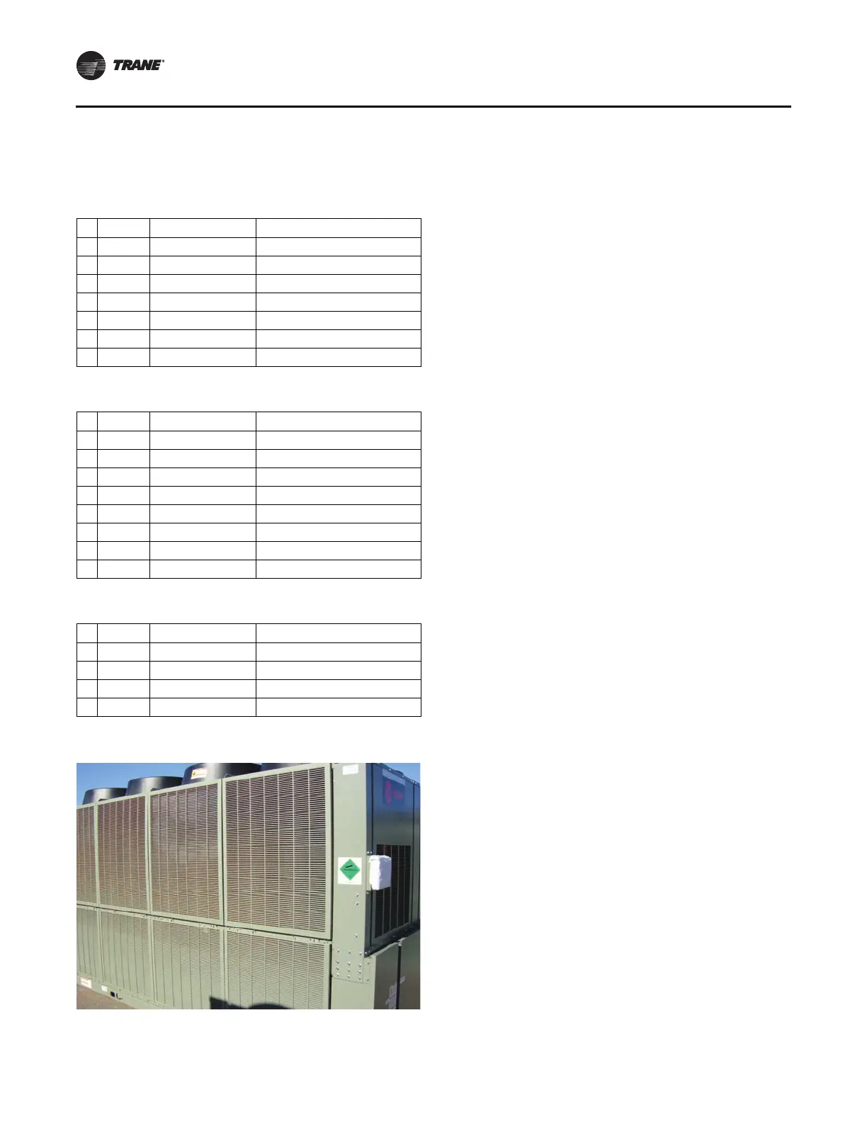
Figure 17. CGAM100–120 ton (W2 units); 1 of 1
Note: Do not use an im
pact gun when installing plastic
louvers.
1. Install three clips (Figure 18, p. 23, Item 2) per upper
louver.
2. Instal
l eight upper louvers (Figure 18, Item 1), four
each side, w
ith provided M8 X 16 sc
rews (Figure 18,
Item 3).
Note: If installing the half louver option, the
instal
lation is complete at this point.
3. Install two louver support angles (Figure 18, Item 4),
on
e each si
de of unit, with provided M8 X 16 screws
(Figure 18, Item 3).
4. Install eight lower louvers (Figure 18, Item 5), four each
side, with provided M8 X 16 screws (Figure 18, Item 3).
5. Install rear louver angle (Figure 18, Item 6) with
provided M8 X 16 screws (Figu
re 18, Item 3).
6. Install lower end louvers (Figure 18, Item 7 and Item 8)
with provided M8 X 16 screws (Figure 18, Item 3).