Installation
24 PART-SVN228B-EN
CGAM130 Chillers (W3 Units)
Table 29. Kit contents LVR01107
# Qty Per Component Part Component Description
1 10 571272480100 PANEL; LVRD UPPER PLASTIC
2 30 X32030872010 CLIP-SPEED; S Type Spring
3 48 X25020604010 SCREW;M8 X 1.25MM X 16MM
4 2 572024130100 ANGLE; LOUVER
5 10 572055580100 LOUVER; LOWER SIDE CGAM
6 1 572018650100 ANGLE; LOUVER
7 1 572229070100 PANEL; LOUVER W
8 1 572229080100 PANEL; LOUVER W w/o PUMP
Table 30. Kit contents LVR01109
# Qty Per Component Part Component Description
1 10 571272480100 PANEL; LVRD UPPER PLASTIC
2 30 X32030872010 CLIP-SPEED; S Type Spring
3 48 X25020604010 SCREW;M8 X 1.25MM X 16MM
4 2 572024130100 ANGLE; LOUVER
5 10 572055580100 LOUVER; LOWER SIDE CGAM
6 1 572018650100 ANGLE; LOUVER
7 1 572229070100 PANEL; LOUVER W
8 1 572229090100 PANEL; LOUVER, W w/PMP
Table 31. Kit contents LVR01108
# Qty Per Component Part Component Description
1 10 571272480100 PANEL; LVRD UPPER PLASTIC
2 30 X32030872010 CLIP-SPEED; S Type Spring
3 28 X25020604010 SCREW;M8 X 1.25MM X 16MM
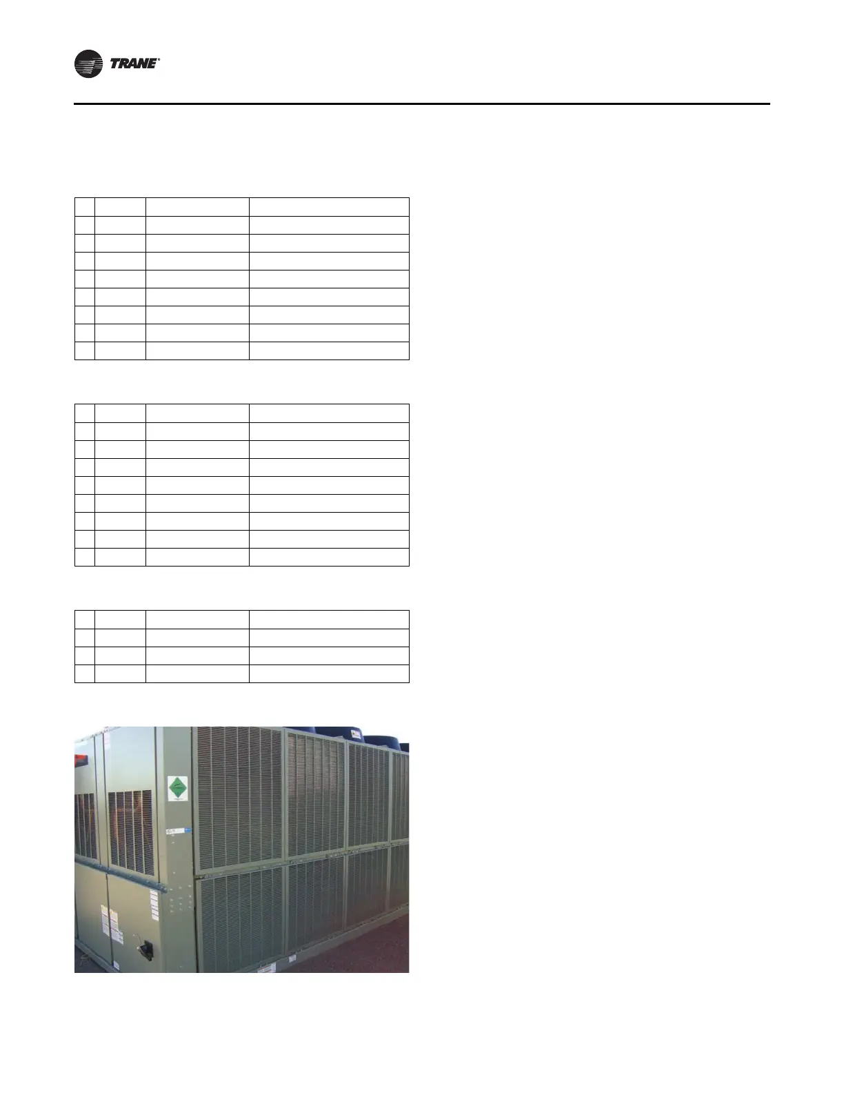
Figure 19. CGAM130 ton (W3 units); 1 of 1
Note: Do not use an im
pact gun when installing plastic
louvers.
1. Install three clips (Figure 20, p. 25, Item 2) per upper
lo
uver.
2. Instal
l ten upper louvers (Figure 20, Item 1), five each
side, with pro
vid
ed M8 X 16 screws (Figure 20, Item 3).
Note: If installing the half louver option, the
instal
lation is complete at this point.
3. Install two louver support angles (Figure 20, Item 4),
one each si
de of unit, with provided M8 X 16 screws
(Figure 20, Item 3).
4. Install ten lower louvers (Figure 20, Item 5), five each
side, with provid
ed M8 X 16 screws (Figure 20, Item 3).
5. Install rear louver angle (Figure 20, Item 6) with
provid
ed M8 X 16 screws (Figu
re 20, Item 3).
6. Install lower end louvers (Figure 20, Item 7 and Item 8)
with provided M8 X 16 screws (Figure 20, Item 3).