EasyManua.ls Logo

Trane EXHF User Manual

Trane EXHF
118 pages
To Next Page IconTo Next Page
Page #1 background imageLoading...
Page #1 background image
SAFETY WARNING
Only qualified personnel should install and service the equipment. The installation, starting up, and servicing of
heating, ventilating, and air-conditioning equipment can be hazardous and requires specific knowledge and training.
Improperly installed, adjusted or altered equipment by an unqualified person could result in death or serious injury.
When working on the equipment, observe all precautions in the literature and on the tags, stickers, and labels that
are attached to the equipment.
GEHE 006-060 - 50/60 Hz
A” and later
GEHE 006-060 - 50/60 Hz
GEHE 072-180 - 50/60 Hz
“D” and later
GEHE 072-300 - 50/60 Hz
EXHF 018-070 - 60 Hz
A” and later
EXVF 018-070 - 60 Hz
Installation, Operation,
and Maintenance
Water Source Heat Pump
Axiom™ Horizontal/Vertical
GEHE/GEVE, EXHF/EXVF
½–25 Tons, 60 Hz
March 2012
WSHP-SVX01L-EN

Table of Contents

Question and Answer IconNeed help?

Do you have a question about the Trane EXHF and is the answer not in the manual?

Trane EXHF Specifications

General IconGeneral
BrandTrane
ModelEXHF
CategoryHeat Pump
LanguageEnglish

Summary

Safety and Warnings

General Safety Warnings

Includes warnings for field wiring, PPE, UV lights, and microbial growth.

Environmental and Refrigerant Practices

Details on environmental concerns related to refrigerants and responsible handling.

Model Number Descriptions

GEH/GEV Model Number Breakdown

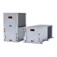
Explains the coding for GEH/GEV unit configuration, capacity, and voltage.

EXH/EXV Model Number Breakdown

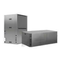
Explains the coding for EXH/EXV unit configuration, capacity, and voltage.

Manual Overview and Unit Information

Overview of Manual

Describes the manual's purpose and customer property status.

Unit Nameplates and Model Description

Location and importance of unit/compressor nameplates and model number breakdown.

Pre-Installation Procedures

Unit Inspection and Jobsite Readiness

Checklists for inspecting units for shipping damage and verifying jobsite conditions.

Jobsite Storage Guidelines

Recommendations for proper unit storage to prevent damage and microbial growth.

Unit Dimensions and Clearances

GEH/EXH Service Clearances

Minimum required clearances for accessing GEH and EXH units for service.

GEV/EXV Service Clearances

Minimum required clearances for accessing GEV and EXV units for service.

Unit Weights

Net and shipping weights for various GEH, GEV, EXH, and EXV unit sizes.

Installation Procedures

General Installation Checks

Essential checks to perform for successful unit installation.

Electrical Wiring and Grounding

Guidelines for safe and compliant main power wiring, grounding, and low-voltage connections.

Ductwork and Drain Connections

Instructions for installing supply/return ductwork and condensate drain lines.

Hanging and Support Requirements

Procedures for hanging horizontal units and providing support.

Waterside Economizer Installation

Detailed steps for installing the optional waterside economizer system.

Economizer Start-Up Sequence

Cooling Mode Start-Up

Steps for setting up the unit for cooling operation with economizer.

Heating Mode Start-Up

Steps for setting up the unit for heating operation with economizer.

Electrical Data

Standard Motor Electrical Data

Electrical specifications for standard motor models (½-5 tons).

ECM Motor Electrical Data

Electrical specifications for ECM motor models (1½-6 tons).

Pre-Start Checklist

System Device Checks

Comprehensive checklist of system devices to verify before unit energization.

Start-Up Procedures

Initial Unit Start-up

Step-by-step guide for initial unit start-up procedures in cooling and heating modes.

Start-Up Checklist and Data Log

Checklist and data log for verifying system operation before full use.

Operating Pressures and Water Data

Tables detailing operating pressures, water pressure drops, and water volumes.

Troubleshooting

Deluxe Control Diagnostics

Interpreting diagnostic LEDs for troubleshooting unit control system issues.

Common Unit Problems and Solutions

Table listing common problems, their causes, and recommended corrections.

Wiring Diagrams

Basic, Deluxe, and Tracer Wiring Diagrams

Illustrations of wiring for basic, deluxe, and Tracer control systems.

Isolation Valve Wiring Connections

Table detailing isolation valve wiring connections by control type.

Warranty Information

Standard Warranty Coverage

Details on Trane's standard parts-only warranty terms.

Extended Warranty Options

Information about optional extended warranty coverage periods.

Related product manuals