FAXA-SVX01B-EN 49
Installation
installation
procedure
Wiring the Remote Human
Interface
The remote human interface requires 24
VAC + 4 volts power source and a
shielded twisted pair communication link
between the remote panel and the
interprocessor communication bridge
(ICPB) module at the self-contained unit.
Note: To prevent control malfunctions,
do not run low voltage wiring (30 volts or
less) in conduit with higher voltage
circuits.
Field wiring for both the low voltage
power and the shielded twisted pair must
meet the following requirements:
1. All wiring must be in accordance with
NEC and local codes.
2. Reference Table I-IP-3 on page 46 for
recommended wiring distance and size.
3. Communication link wiring must be 18
AWG shielded twisted pair (Belden
8760, or equivalent).
4. Communication link must not exceed
5,000 feet maximum for each link. See
Table I-IP-2 on page 35.
5. Do not run communication link
between buildings.
WARNING
Hazardous voltage!
Before servicing unit, disconnect
electrical power source and remote
disconnects. Failure to do so may
cause death or injury.
WARNING
Disconnect gas supply!
Before servicing unit, FIRST turn off
the gas supply. Failure to turn off the
gas supply can cause death or serious
injury.
Low Voltage (AC) Field Wiring
Connections
To access the wire entry locations, open
the RHI panel door and remove the two
screws on the right-hand side of the key
pad. Swing the keypad open, exposing
both the wire entries and the back of the
HI module. Refer to Figure I-IP-7 on page
48 and connect one end of the three
conductor 24 volt wires to the remote
panel terminal strip (+), (-), and (ground).
Communication Link (Shielded Twisted
Pair) Wiring
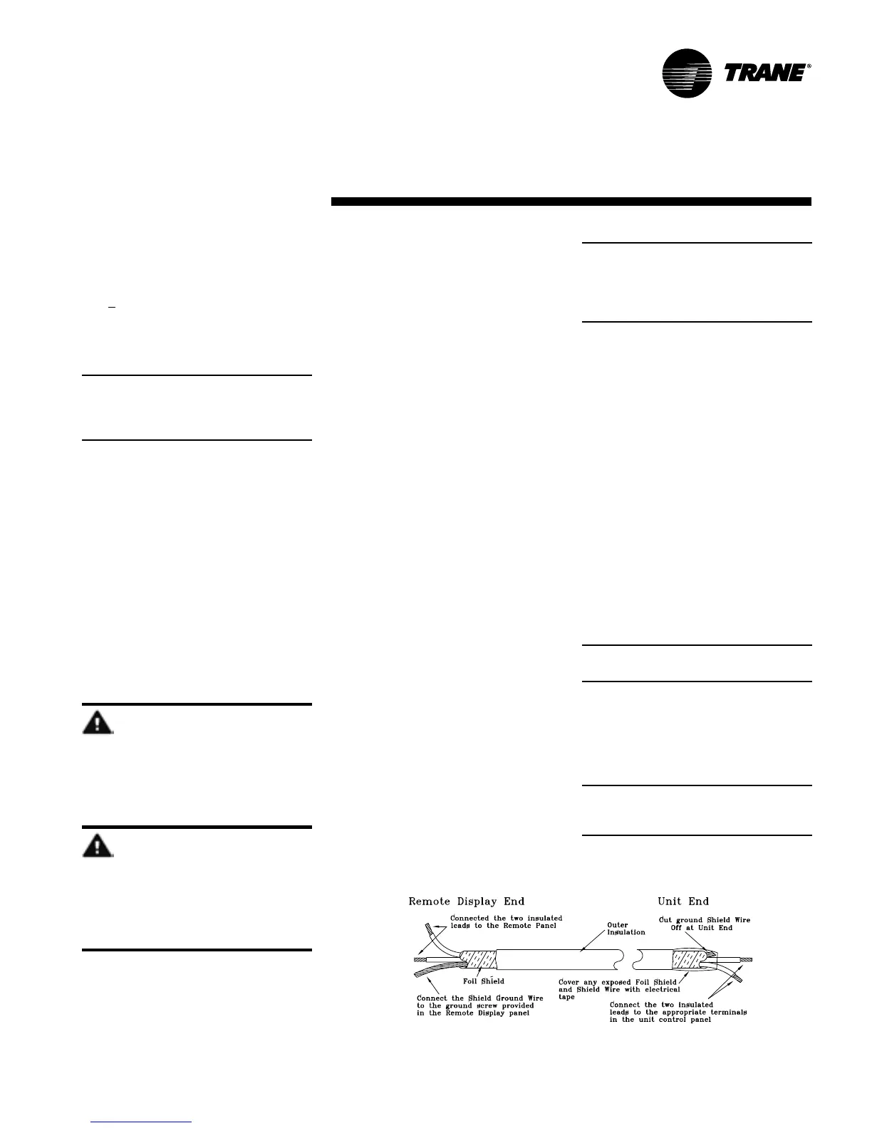
Trim the outer covering of the shielded
cable back approximately one inch. See
Figure I-IP-8. Do not cut the bare shield
wire off. Strip approximately
1
/
2
-inch of
insulation from each insulated wire to
connect them to the terminal strip at the
remote panel.
Connect the white lead to the positive (+)
terminal, the black lead to the negative (-)
terminal, and the bare shield wire to the
terminal at the remote human interface
panel.
Close the key pad plate. Install and
tighten the two screws removed earlier.
Close the outer door and install the
recessed locking screw at the bottom
right hand side of the enclosure to
prevent accidental starting of the unit by
unauthorized personnel while completing
the wiring at the self-contained unit.
At the fresh air unit, connect the opposite
end of the three conductor 24 volt wire to
the appropriate terminal strip as follows:
Note: Although the 24 volt power is not
polarity sensitive, do not connect either
the + (plus) or - (minus) terminals from
the remote panel to ground at the fresh
air unit.
1. Connect the wire connected to the
positive (+) terminal at the remote
panel.
2. Connect the wire connected to the
negative (-) terminal at the remote
panel.
3. Connect the ground wire from the
remote panel to the unit control panel
casing.
Interprocessor Communication Bridge
Module Wiring
Refer to Figure I-IP-8 and trim the outer
covering of the shielded cable back
approximately one inch. Cut the bare
shield wire off even with the outer
covering. Strip approximately
1
/
2
-inch of
insulation from each insulated wire in
order to connect them to the terminal
strip at the unit. Wrap tape around any
exposed foil shield and/or base shield
wire.
Note: The communication link is polarity
sensitive.
Refer to the unit wiring diagram and
connect the white lead to the positive (+)
terminal and the black lead to the
negative (-) terminal. (These terminals
are numbered. Reference to color is for
clarification to maintain polarity).
Note: To maintain polarity, do not
connect the base shield wire to ground
at the fresh air unit.
Figure I-IP-8. Dressing shielded twisted wire