FAXA-SVX01B-EN 53
Installation
general
information
5. Check amp draw at compressor
terminals. RLA and LRA is on the unit
nameplate.
6. Measure amp draw at evaporator and
exhaust fan motor terminals. FLA data
is on the motor nameplate.
7. After the system has stabilized (15 – 30
minutes), check and record operating
pressures and temperatures for all
circuits.
8. Check natural gas pressure and verify
no less than 5” w.c. (0.18 psi) or greater
than 14” w.c. (0.5 psi).
9. Inspect refrigerant flow in the liquid line
sight glass. Flow should be smooth and
even, with no bubbles once the system
has stabilized.
Normal startup can occur provided that
Tracer Summit is not controlling the
module outputs or the generic BAS is not
keeping the unit off.
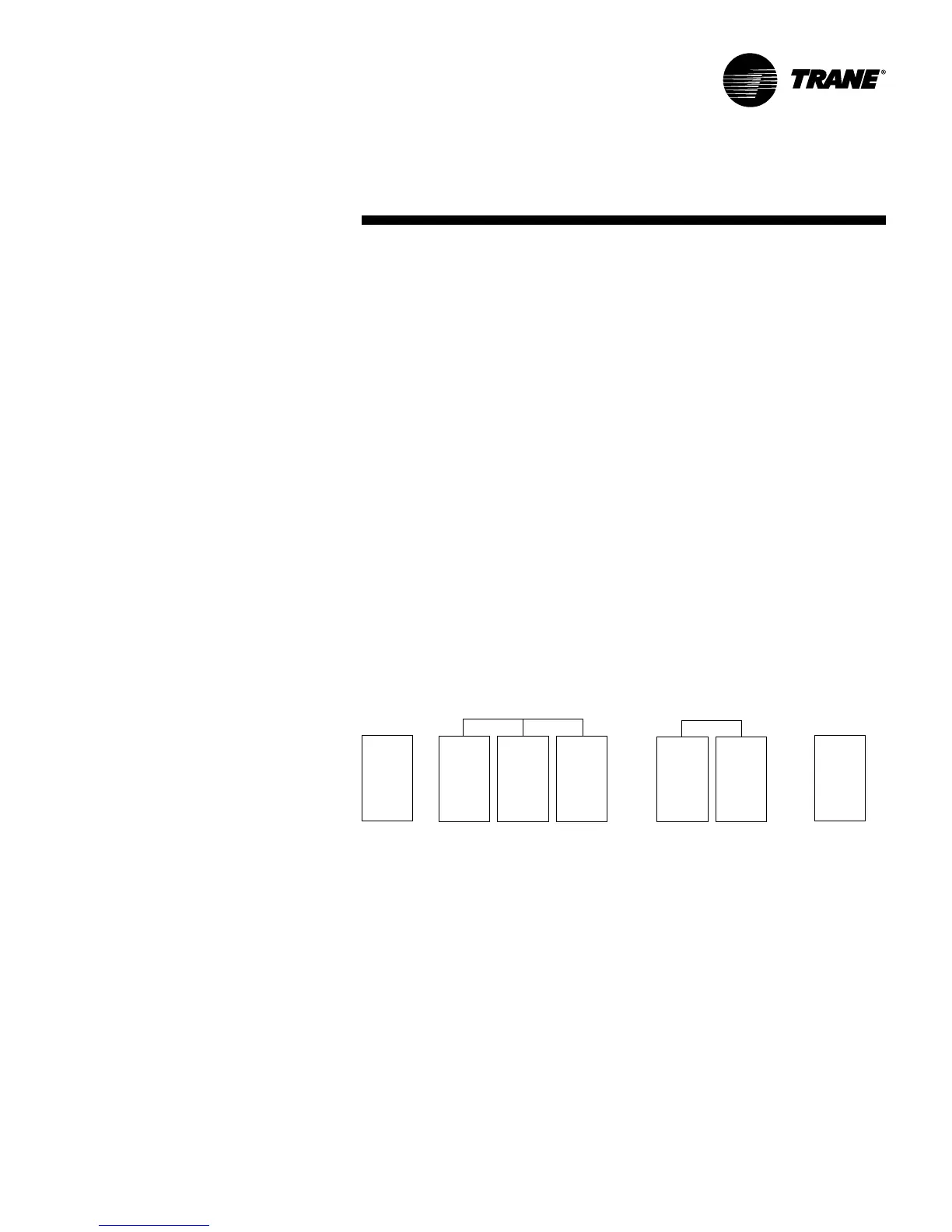
Figure I-S-2. Compressor arrangement for
unit sizes 051 & 066
BC
D
circuit 2
(main)
A
circuit 1
(reheat)
A
circuit 1
(reheat)
circuit 2
(main)
BC
Figure I-S-1. Compressor arrangement for
unit sizes 031 & 044
startup
To ensure that Tracer Summit has no
affect on unit operation, remove Tracer
wiring and make required changes to
setpoint and sensor sources. See the
Packaged Fresh Air Unit Programming
Guide, FAXA-SVP01B-EN,
for more
information.
Unit Startup
Reference the
Packaged Fresh Air Unit
Programming Guide, FAXA-SVP01B-EN,
for unit operating instructions.
A copy
ships with each unit. Also, for units with
gas heat, reference the Reznor
Installation Form RGM 401 for proper
gas heater startup and operation.