FAXA-SVX01B-EN 35
Installation
mechanical
requirements
Condensate Drain Trapping
A fresh air unit is selected for its
dehumidifying capability. As such,
condensate can be formed at an
enormous rate. The Packaged Fresh Air
Unit, drain pan and condensate line have
been sized and designed accordingly. An
often-overlooked element of proper
condensate drainage is trapping. An
incorrectly designed and installed trap on
the piping exiting the drain pan can
restrict the flow of condensate or cause
‘‘spitting’’ or “geysering” of the
condensate water which can dampen the
interior insulation of the air handler and/
or ductwork, creating an opportunity for
mold infestation. The HVAC equipment
manufacturer’s installation and trapping
instructions must be carefully followed to
assure adequate condensate removal
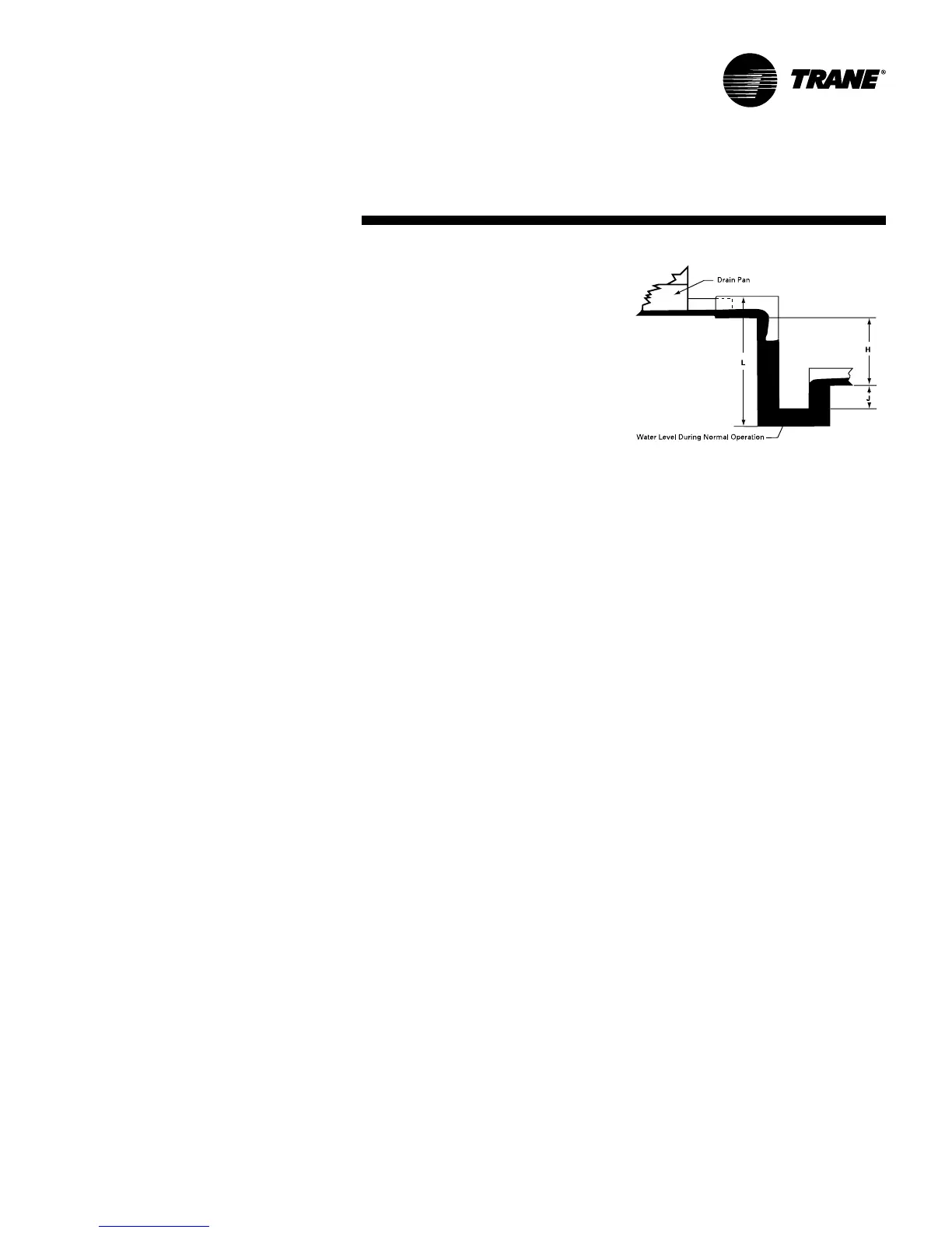
under all operating conditions. Figure I-
MR-2 shows the proper design for a p-
trap design, in an air handler with a draw-
through coil arrangement.
Figure I-MR-2. P-trap design for drain pan
H = (1” for each 1” of maximum negative static
pressure) + 1”
J = half of H
L = H + J + pipe diameter + insulation