RT-SVX51L-EN
23
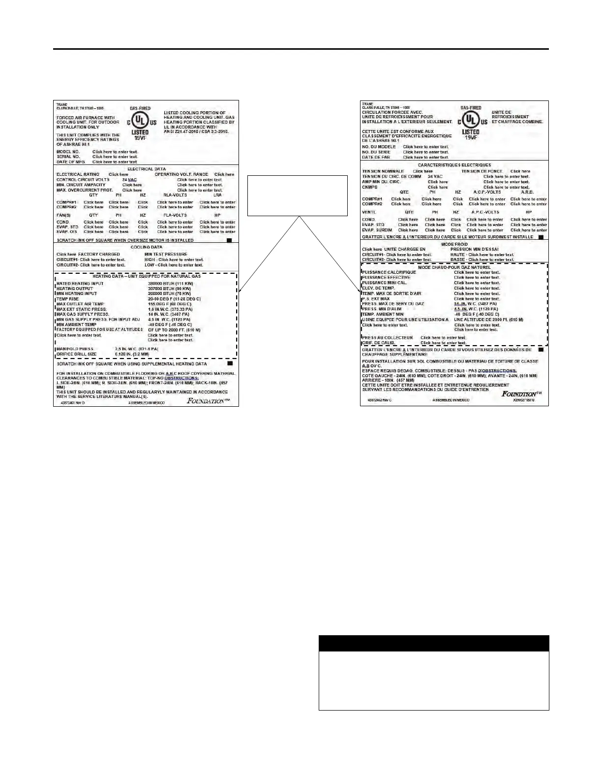
Figure 25. Location for pasting supplemental heating data label
Paste supplemental
heating data label
over the dotted area
Condensate Drain Configuration
An evaporator condensate drain connection is provided on
each unit. Refer to “Dimensional Data,” p. 10 for the
appropriate drain location.
Note: Use 1-inch PVC pipe to connect to the drain pan
outlet provided in the unit. This is a slip fit joint (no
threads). Do not use PVC glue to connect
condensate drain, thread sealing compound or
Teflon tape may be used.
A condensate trap must be installed at the unit due to the
drain connection being on the “negative pressure” side of
the fan.
A condensate drain line must be connected to the P-Trap.
Pitch the drain lines at least 0.5-inch for every 10 feet of
horizontal run to assure proper condensate flow. Do not
allow the horizontal run to sag causing a possible
doubletrap condition which could result in condensate
backup due to “air lock”.
Filter Installation
Each unit ships with 2-inch filters installed. The quantity of
filters is determined by unit size. Access to the filters is
obtained by removing the filter access panel.
Refer to the unit Service Facts (shipped with each unit) for
filter requirements
Note: Do not operate the unit without filters.
Field Installed MERV13 Filters
Optional MERV13 filters are available for purchase.
Replace standard filters with MERV13 Filters according to
the installation instructions provided in the kit.
Field Installed Power Wiring
An overall dimensional layout for the standard field
installed wiring entrance into the unit is illustrated in
“Dimensional Data,” p. 10. To insure the unit’s supply
power wiring is properly sized and installed, follow the
guidelines outlined below.
Note: All field installed wiring must conform to NEC
guidelines as well as state and Local codes.
Verify that the power supply available is compatible with
the unit’s nameplate ratings. The available supply power
must be within 10 percent of the rated voltage stamped on
the nameplate. Use only copper conductors to connect the
power supply to the unit.
NOTICE
Use Copper Conductors Only!
Failure to use copper conductors could result in
equipment damage as the equipment was not
designed or qualified to accept other types of
conductors.
Installation

 Loading...