RT-SVX51L-EN
25
conduit with the high voltage power wiring. 5. Route low voltage wiring as per Figure 27, p. 25.
Table 2. Electromechanical thermostat 24V AC conductors with electromechanical unit
Distance from Unit to Control Recommended Wire Size
0 - 30 feet
22 gauge
0 - 9.1 m 0.33 mm^2
31 - 50 feet
20 gauge
9.5 - 15.2 m 0.50 mm^2
51 - 75 feet
18 gauge
15.5 - 22.9 m 0.75 mm^2
76 - 125 feet
16 gauge
23.1 - 38.1 m 1.3 mm^2
126 - 200 feet
14 gauge
38.4 - 60.9 m 2.0 mm^2
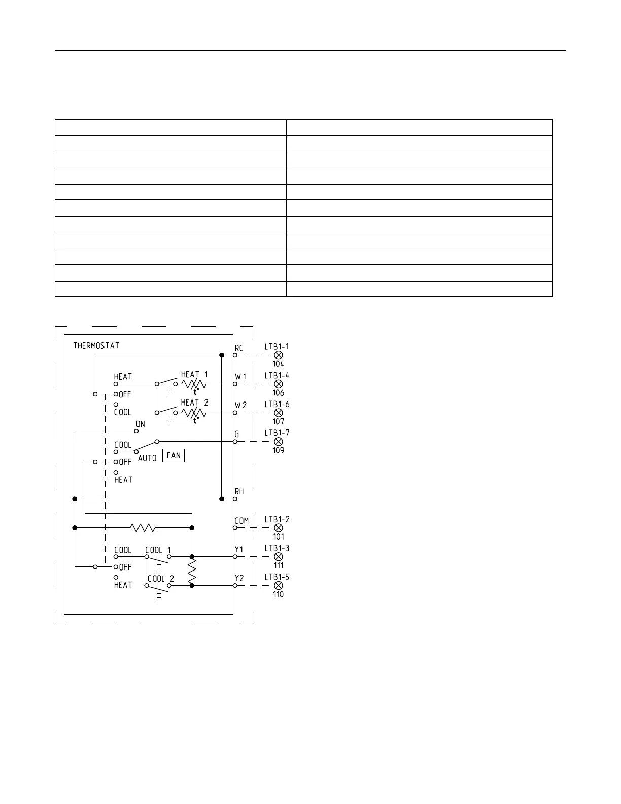
Figure 27. Conventional thermostat field wiring diagram
Requirements of Gas Heat
The unit gas train and optional through-the-base gas shut-
off valve are rated at 0.50 PSIG maximum. A pressure
reducing regulator is recommended to prevent this
maximum from being exceeded. These components must
be isolated during field gas piping test that exceed 0.50
PSIG. It is recommended that the field piping be capped
prior to the unit gas train or optional through-the-base gas
shut-off valve if present.
• Gas supply line properly sized and connected to the
unit gas train.
• All gas piping joints properly sealed.
• Gas piping leak checked with a soap solution. If piping
connections to the unit are complete, do not pressurize
piping in excess of 0.50 PSIG or 14–inch W.C. to
prevent component failure.
• Drip leg installed in the gas piping near the unit.
Installation

 Loading...