WSHP-PRC004-EN10
Features and
Benefits
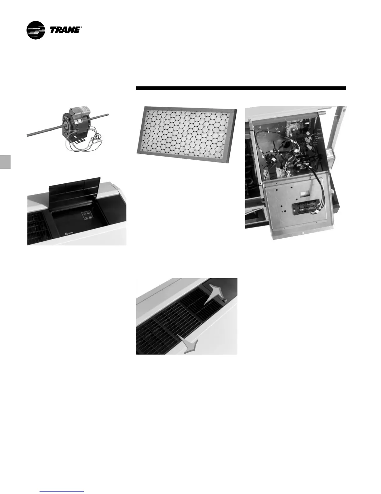
Figure FB-15 – Blower Motor
Blower Motor
The supply-air (blower) motor is a multi-
speed motor with internal thermal
overload protection. The motor bearings
are permanently lubricated and sealed.
Standard motors are rated from 200
CFM at low speed (unit size 006) to 425
CFM at high speed (unit size 015).
All motors are factory wired for low and
high speed options. Switching for speed
control is located in the unit control
panel.
(See Figure FB-15 for blower
motor and Figure FB-16 for fan switching
control panel.)
See fan performance section for factory
ratings of low and high speed settings.
Air-Side Filter
The air-side filter incorporates a 1-inch
[25.4 mm] thick (nominal) disposable
fiberglass option. The filter includes an
average synthetic dust weight arrestance
of approximately 75%. This dust holding
capability includes a colorless, odorless
adhesive to retain dirt particles within
the filter media after fiber contact.
The filter is accessible through the
return-air portion of the unit subbase.
Panel removal is not necessary to
facilitate filter maintenance for the
standard height unit configuration.
Figure FB-16 – Fan Switch Control Panel
Figure FB-17 – Filter Media
Supply-Air Registers
Supply-air registers for the GECA
product are constructed of a plastic,
corrosive resistive material. The registers
include a snap-in deflection design to
simplify installation, as well as facilitate
the ability to apply a bi-directional
arrangement across the register.
Hinged Control Box
Controls for the console unit are housed
on the right-hand side of the chassis. The
box dwells above the refrigeration
section of the chassis.
Access to the controls are made by way
of a hinged control box. This hinged box
allows easy access for service and
installation of the controls portion of the
chassis.
Figure FB-18 – Bi-directional Registers
Figure FB-19 – Hinged Control Box