15
WSHP-PRC004-EN
Features and
Benefits
Basic 24V
Controls
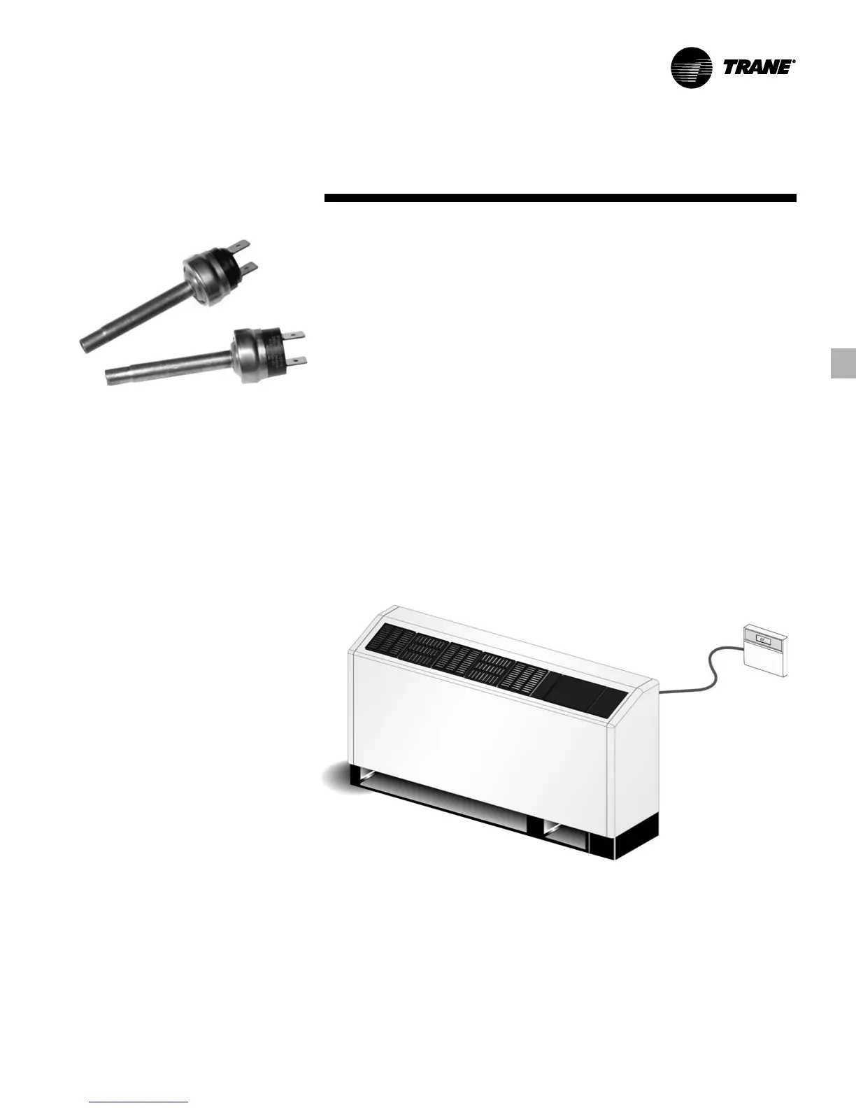
Figure FB-28 – Low and High Pressure
Switches
Stand-alone System
The 24V electro-mechanical design may
be applied as a stand-alone control
system. The stand-alone design provides
accurate temperature control directly
through a unit mounted controller, or a
wall-mounted mercury bulb or electronic
thermostat. This system setup may be
utilized in a replacement design where a
single unit retrofit is needed. It may be
easily interfaced with a field provided
control system by way of the factory
installed 18-pole terminal strip.
This stand-alone control is frequently
utilized on lower volume jobs where a
building controller may not be
necessary, or where field installed direct
digital controls are specified. This type of
control design does require a constant
flow of water to the water source heat
pump. With a positive way to sense flow
to the unit, the units safety devices will
trigger the unit off.
The stand-alone system design provides
a low cost option of installation while still
allowing room control freedom for each
unit.
See Figure FB-29 for 24V stand-
alone system controls.
Safety Devices
All unit safety devices are provided to
prevent compressor damage.
Low Pressure Switch
The low pressure switch prevents
compressor operation under low charge,
excessive loss of charge situations, and
under low temperature operation. This
device is installed on the suction side of
the refrigeration circuit. It is set to
activate at refrigerant pressures of 20
psig to fit most applications.
High Pressure Switch
The high pressure switch prevents
compressor operation during high or
excessive discharge pressures. This
device is located on the discharge side of
the compressor. The pressure switch de-
energizes the compressor when
discharge pressure exceeds 395 psig.
See Figure FB-28 for pressure switches.
Lockout Relay
The lockout relay works with the low and
high pressure switch to prevent
compressor operation if the unit is under
low or high refrigerant circuit pressure,
or condensate overflow conditions. The
lockout relay may be reset at the
thermostat, or by cycling power to the
unit.
General alarm is accomplished through
the lockout relay and is used for driving
light emitting diodes (LEDs). This feature
may be used to drive field supplied
relays, but cannot be used to drive field
installed control inputs.
Figure FB-29 – 24V Stand-alone System Controls